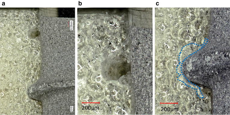
Fig. 3.

Representative photographs of ST/simulated bone interface. Photographs of a and b were taken from the neck of the implant, showing the tapped channel (a: magnification, ×30, b: magnification, ×40). A photograph of c was taken from the middle of the implants, showing the white layer (dotted line) (magnification, ×40)
