
Fig. 6.
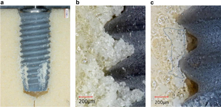
Representative photographs of MK4/simulated bone interface. Debris was scattered overall implant body and the cutting chamber (a: magnification, ×4). A photograph of b and c was taken from the middle of the implant (magnification, ×40), and b was showing debris in the threads root, and after air-blowing of c was showing the white layer (dotted line), the space realized thread root (magnification, ×40)