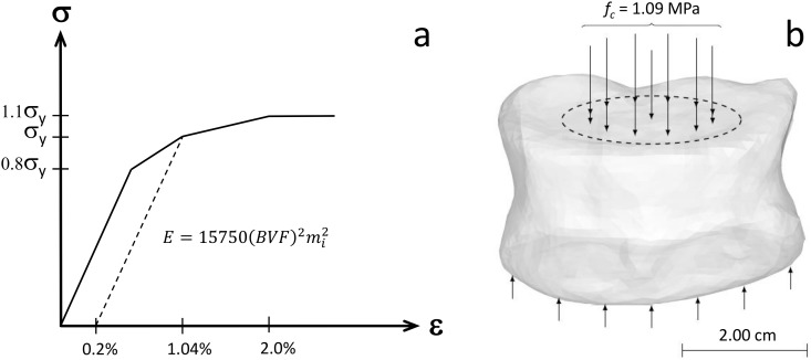
Fig 1. Finite Element Analysis setup.
(a) Principal material direction stress-strain response mapped to the elements of the FE meshes. The mi is the normalized eigenvalue of the fabric tensor corresponding to the specific orthotropic plane. The modulus-BVF-fabric relationship was introduced by Garcia et al. [49]. The yield strain, 1.04%, is in accordance with the study of Bayrakhtar et al. [50]. The corresponding yield stress (σy) was determined based on a 0.2% offset rule. Ultimate stress was set to 1.1σy in accordance with the study of Helgason et al. [53]. (b) A compressive load of fc = 1.09 MPa was evenly distributed over the estimated nucleus pulposus contact area of the FE models. The models were constrained against displacement in all directions on the inferior side of the vertebrae.

