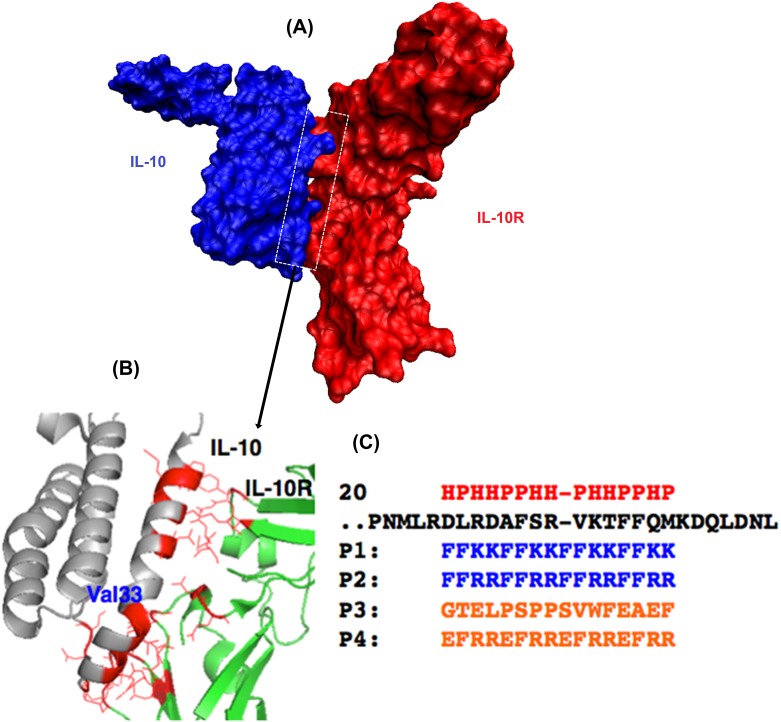
Fig 1. Illustration of peptide design.
(A) A space-filling model of the interface structure of the IL-10/IL-10R protein–protein complex. (B) An expansion of the interface between the two proteins to indicate a few residue to residue contacts. The complex structure of IL-10 (Grey) and IL-10R1 (Green) along with the binding interface (Red). Val33 indicates the location of a helical bend for the binding helix. (C) Mimicking of this interface could produce an antagonist to inhibit the interaction. The binding helical region of IL-10 (black) is aligned with designed peptides (P1 and P2[38] in Blue) along with the hydrophilic/hydrophobic (HP) pattern (Red). Two control peptides (P3 and P4) are also shown (Orange).

