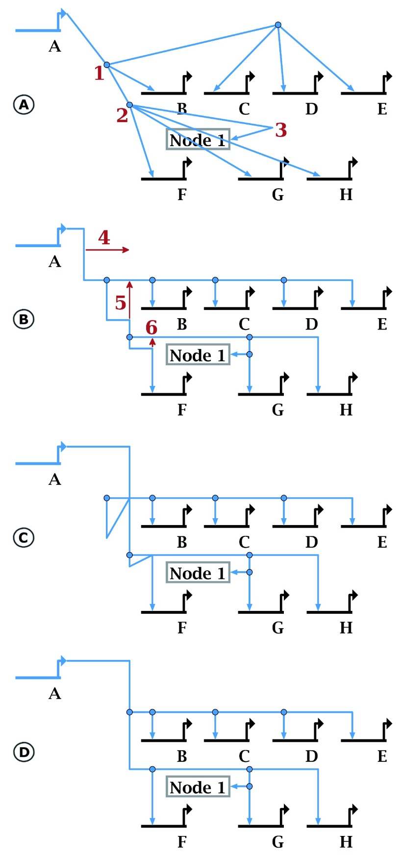
Figure 3. New drawing tools.
The new orthogonalization tool (here we use Layout->Fix All Non-Orthogonal Segments->Minimize Shifts) takes existing “roughed-in” hyperedge geometry ( A) and tweaks it so it is orthogonal ( B). The resulting geometry is not generally optimal, since corner points (e.g. those labeled red 1 and 2 in ( A) are often retained. Gross features such as the 180-degree turn at red 3 must be provided to guide placement. In ( C), the user can quickly drag segments (red arrow 4) and corner points (red arrows 5 and 6). Although these changes create a severely malformed link tree, the overlap tool can repair it, making this approach a quick and easy shortcut for editing tree geometry. Selecting Layout->Clean Up All Overlapping Link Tree Geometry produces the clean result in ( D).

