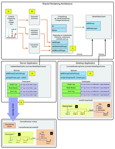
Figure 5. Architecture of dual-platform rendering pipeline.
This is the architecture of the rendering pipeline. ( A): Each drawing class (e.g. a Gene) knows how to render the final glyph from primitive geometric shapes; additional shapes are also used to render the “selected” version. The classes also encapsulate information needed to perform intersection testing. ( B): In the desktop application, the logic for determining point intersections is provided by drawing class functions. In the server application, the rendering pipeline gets a list of intersection boundaries from each drawing class instance, and stores them in the CacheGroup. ( C): The concrete CacheGroup implementations have differing interfaces, depending on what needs to be exported to the web client while running as a server application. Shapes are added to the CacheGroups, which are then added to the ModelObjectCache; the concrete type of the ModelObjectCache depends on the target platform, as illustrated. ( D): In the server application, the addGroup() method of the VisitableObjectCache stores concrete CacheGroups to an array matching the appropriate DrawLayer. ( DrawLayers are used to organize the overall order of what is drawn first to last.) The CacheGroups are stored intact for serialization when the web client requests a model rendering update. The accept() method enables iterating through stored CacheGroups per DrawLayer. Alternately, in the desktop application, the addGroup() method of the ConcreteGraphicsCache extracts the primitive shapes from the CacheGroup and stores the shapes to an array matching the appropriate DrawLayer. The render() method then draws the stored shapes to a Graphics2D object given a DrawLayer. ( E): CacheGroup instances are not directly serialized for transmission. Instead, a helper class is used depending on the CacheGroup’s type; that is then serialized to JSON format.

