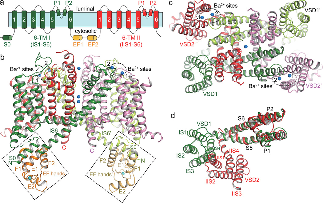
Figure 2. Overall structure of AtTPC1.
a, Topology diagram of AtTPC1. b, Side view of an AtTPC1 channel dimer. 6-TM I, 6-TM II, and EF hands from one subunit are shown in green, red and orange, respectively, and from the other symmetry related subunit are shown in lime green, purple and light orange, respectively. The cytosolic EF-hand domains with bound Ca2+ (cyan sphere) in EF-1 are boxed and the two luminal Ba2+ (blue spheres labeled 1 and 2) binding sites are circled. c, AtTPC1 viewed from luminal side. d, Superposition between the two 6-TM domains using the pore domains in the alignment. The orientation of 6-TM I is the same as that in c.

