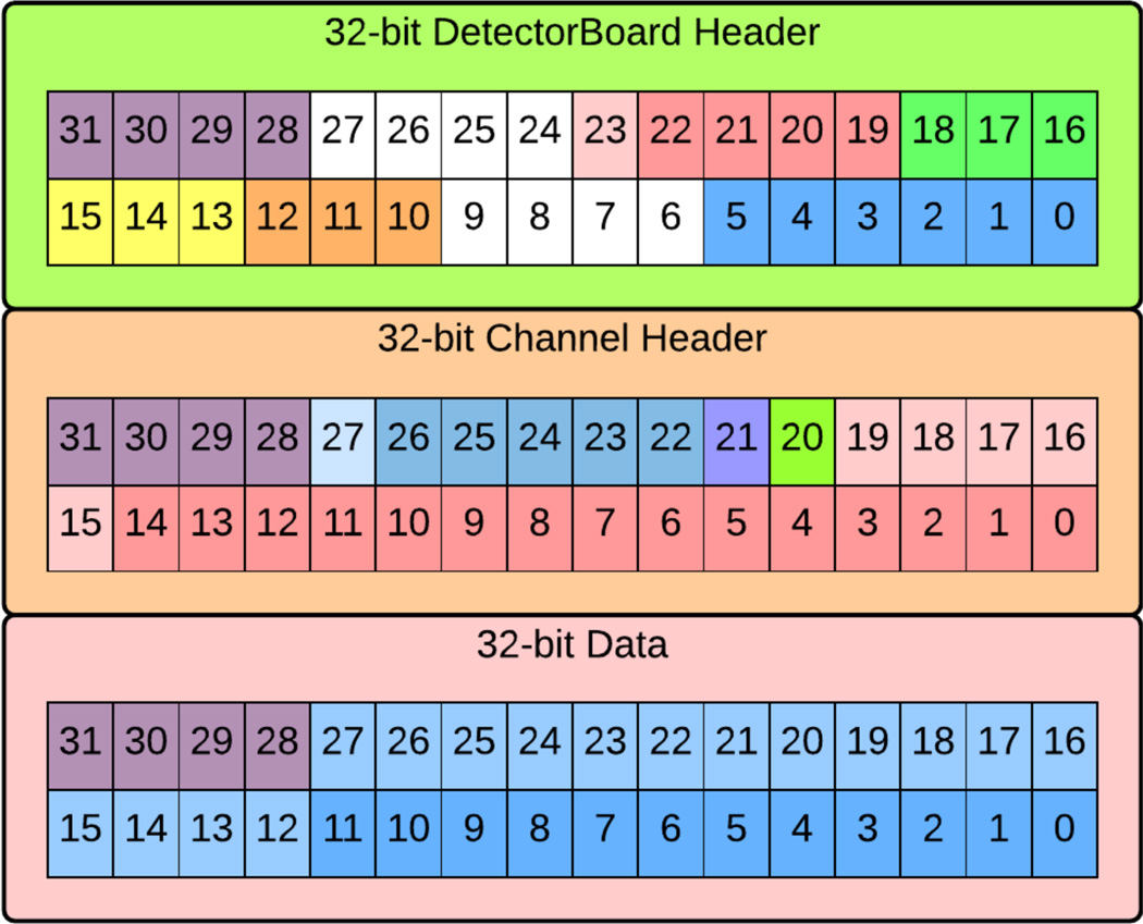
Fig. 10.
Data path headers and samples for Scope Mode. Detector Board header starting at LSB: (5:0) Number of channel header packets, (9:6) not used, (12:10) Detector Board Address, (15:13) DUC Address, (18:16) MB Address, (23:19) Data Format, (27:24) not used, (31:28) Packet ID (must equal to 0×4). Channel Header starting from LSB: (19:0) TDC data (if used), (20) hardware trigger hit (energy), (21) firmware trigger hit, (27:22) channel address, (31:28) Packet ID (must equal to 0×3). ADC data sample starting from LSB: (27:0) e.g. raw ADC data from (11:0), (31:28) Packet ID (must equal to 0×1).

