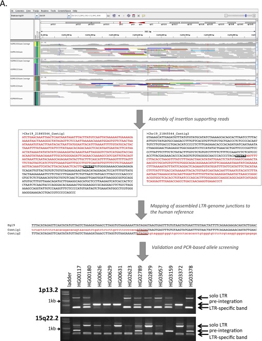
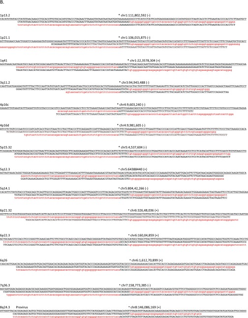
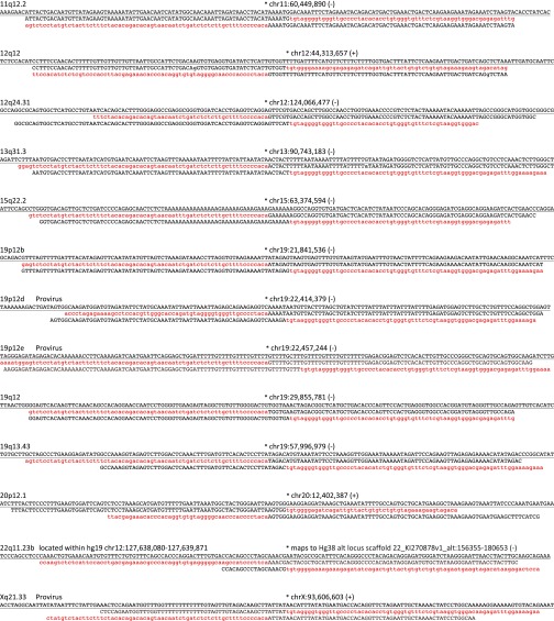
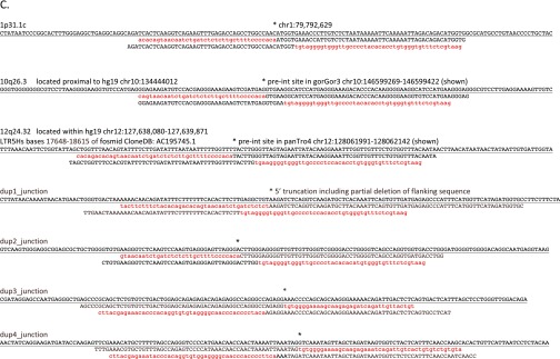
Fig. S1.
Assembly-based identification and validation of nonreference HML-2 insertions. (A, Upper) Integrative Genomics Viewer (IGV) screen shot showing Illumina paired short reads from four HGDP samples mapped to a candidate nonreference HML-2 insertion. The K113 locus at chr19:21,841,544 is illustrated as an example. Read pairs that have both reads mapped to the reference are shown in gray. Anchored reads that have discordant mated pairs (i.e., mapped to HML-2 LTRs that are present in the hg19 reference) are flagged and shown in color, and split reads (representing putative captured viral-genome junctions) are multicolored. Nearby SNPs are indicated by colored vertical lines within individual reads. HML-2 LTR-supporting read pairs, as reported in RetroSeq outputs, were then subjected to a local de novo assembly to generate contigs (boxed) corresponding to the 5′ and 3′ K113 proviral junctions. The sequence corresponding to the HML-2 LTR is shown in red; the sequence that maps to the reference is shown in black; and the candidate TSD is in shown dark red and underlined. (A, Middle) Alignment confirming overlap of the assembled contigs and presence of the TSD to the hg19 reference. Coloring is as above; the sequence corresponding to the reference is underlined. (A, Lower) Example validation screening is shown for integrations at 1p13.2 and 15q22.2 across a subset of 12 samples from the 1KGP. Each PCR contained three primers: two were designed to flank the insertion site, and a third primer was specific for the 5′ edge of the HML-2 LTR. Potential amplicons are interpreted to represent the preintegration site, solo-LTR (∼968 bp larger than the empty site), or an LTR-specific band. 2-LTR proviruses will not be amplified, but should produce an LTR-specific band. (B) Three-way alignments show overlap of HML-2–genome junctions against the hg19 reference (empty allele) for 27 validated nonreference insertions identified by breakpoint assembly. In each alignment, the reference allele is underlined and the sequence corresponding to the edges of either the 5′ or 3′ HML-2–LTR junction is shaded in red (LTR) or black (flanking). The hg19 insertion coordinates and locus are provided above each alignment; the asterisk indicates the first base of the LTR, respective of orientation (as indicated by “+” or “−” symbol). (C) Alignments corresponding to insertions identified in mining of unmapped reads. The junctions for five of seven insertions were validated in this study; the remaining two loci have been validated elsewhere (refer to main text). Sequences are shaded as above.


