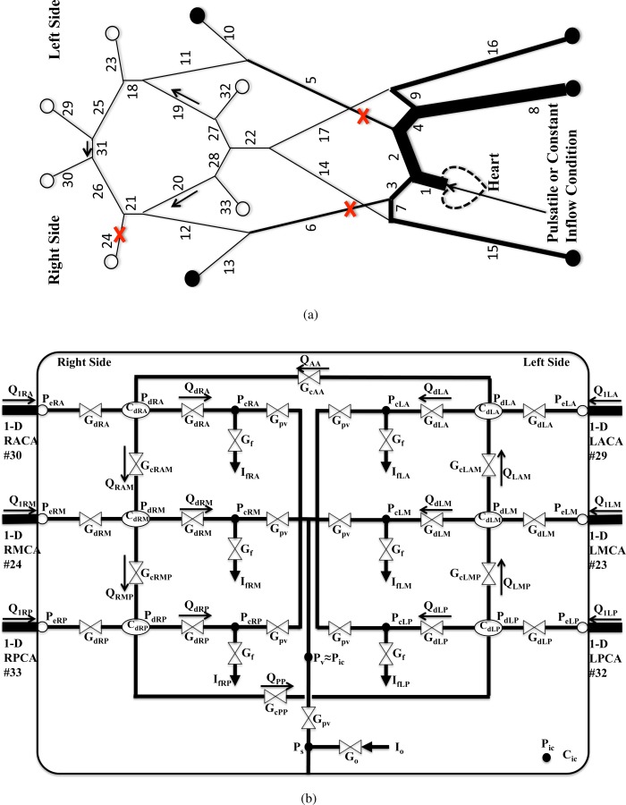
Fig. 1.

(a) Schematic of the 1D arterial network. Outflow boundaries marked with are coupled with the LP network in (b), and boundaries marked with are coupled to three-element Windkessel models. Locations where A 0 is varied are marked with . (b) Schematic of the LP network model, which includes CA. The bounding box represents intracranial space, and a single ICP model is shared by the six cerebral distal vascular bed models inside the intracranial space.
