
Fig. 5.
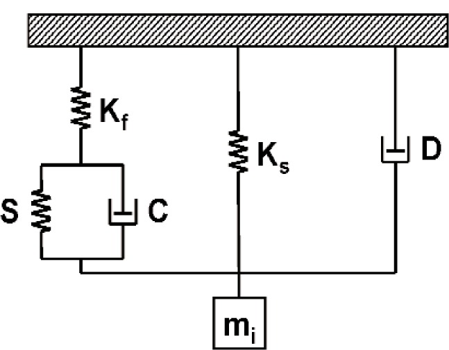
Schematic illustration of a dynamic model for an instrumented indentation system. Kf represents the load-frame stiffness, Ks represents the stiffness of the springs, D and mi represent the damping characteristics and mass, respectively, of the instrument, and S and C represent the storage and loss components, respectively, of the mechanical impedance related to the tip-sample contact.