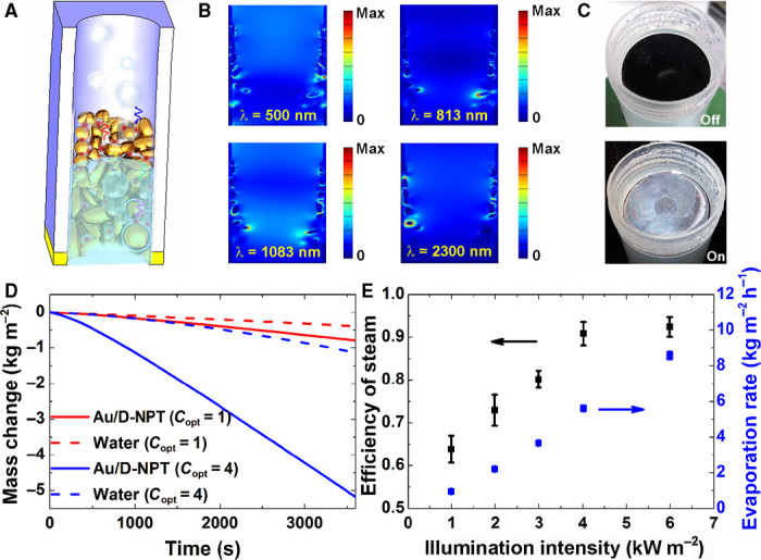
Fig. 4. Plasmonic absorbers for solar steam generation.

(A) Schematic of the solar steam experiment. (B) Calculated cross-sectional electric field distributions at four arbitrary wavelengths. (C) Experimental setups for solar steam generation with the solar simulator off (upper) and on (lower). (D) Evaporation mass change of water with (solid lines) and without (dashed lines) the plasmonic absorbers (Au/D-NPT) as a function of time under different solar irradiations: 1 kW m−2 (red line) and 4 kW m−2 (blue line). (E) Solar steam efficiency (black, left-hand side axis) and evaporation rate (blue, right-hand side axis) with plasmonic absorbers as a function of illumination intensity on the absorber surface.
