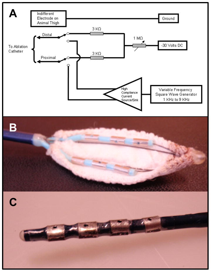
Figure 2.

(A) Prototype direct current injection circuit. Direct current was delivered to the electrodes of the catheters described below from a 30 V regulated DC power supply with the positive terminal of the power supply connected to the grounding patch on the animal's thigh. The negative terminal of the DC power supply was connected through matched, fixed and variable resistors to the electrodes. A 6 kilo-ohms resistance was placed between the electrodes to provide adequate decoupling of the electrodes for good signal acquisition. The negative DC current injected independently to the electrodes could be varied from 10 to 7500 micro amps. (B) Prototype multi-array catheter with two rows of 3 electrodes (3.3 mm, 2mm spacing) with irrigation hole in the middle of each electrode and insulated on one side with polyester fabric to provide a wide area of ablation in the oblique sinus, and (C) Prototype quadripolar (3.2 mm electrodes, 3 mm spacing) catheter insulated on one side with polyester.
