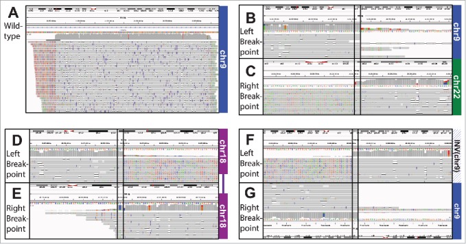
Figure 3.

IGV screenshot alignment of WT (SV02). B-C) IGV Screenshot of Translocation (SV01) alignment. B) Shows the alignment to the area in chr9 and C) the alignment to the area in chr22. Note the erroneous extension of the read past the breakpoint in the bottom left. D-E) IGV Screenshot of Interstitial Deletion (SV05) alignment. The plot shows the alignment to the area upstream D) and downstream E) of the deletion in chr18. Note the erroneous extension of the read past the breakpoint in the top right. F-G) IGV Screenshot of Inversion (SV09) alignment. The plot shows the alignment to the inverted area F) and G) the area downstream of the inversion. We have flipped G) to show how the 2 parts align. Note the erroneous extension of the read past the breakpoint in the top left.
