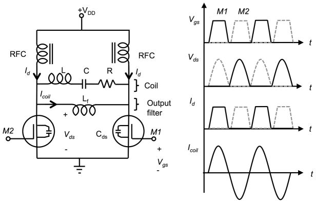
Figure 1.
Schematic Diagram of the CMCD stage. Voltage and current waveforms for MOSFET 1 (M1) and MOSFET 2 (M2) are shown in solid line and grey dash line respectively. The resonant filter formed by Lf and Cds filters out higher harmonics from the drain current source and the fundamental component is recovered on the coil.

