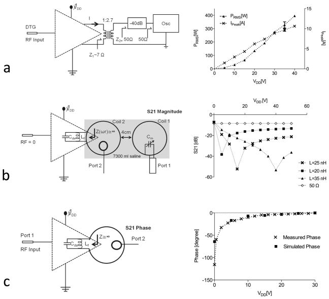
Figure 3.
Peak power and current measurement using an impedance transformer connected to the CMCD output that loads amplifier with approximately 7 Ω when a 50 Ω load is connected to the secondary winding and drain voltage is changed manually across the expected operating range (a). Inter-element isolation of two non-overlapping coils vs. drain voltage provided by the amplifier’s output impedance. Isolation varies with voltage due to the voltage-modulated drain-source capacitance Cds of the power MOSFET (b). Effect of this modulation on the phase of the RF carrier (c).

