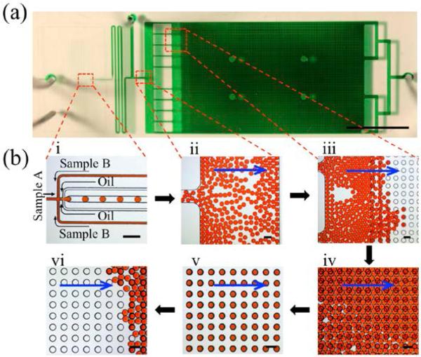
Figure 4.
Images depicting the workflow for the Floating Droplet Array. (a) Photographic image of entire microfluidic device. The device was filled with green dye for visualization, scale bar = 1 cm; (b) Microscopic images of the workflow including (i) droplet generation, (ii) droplet loading into the chamber, (iii) droplet trapping, (iv) filling the chamber, (v) purging extraneous droplets, and (vi) droplet recovery by flipping. Blue arrows in (ii–vi) represent flow direction. All scale bars for (b) = 200 μm.

