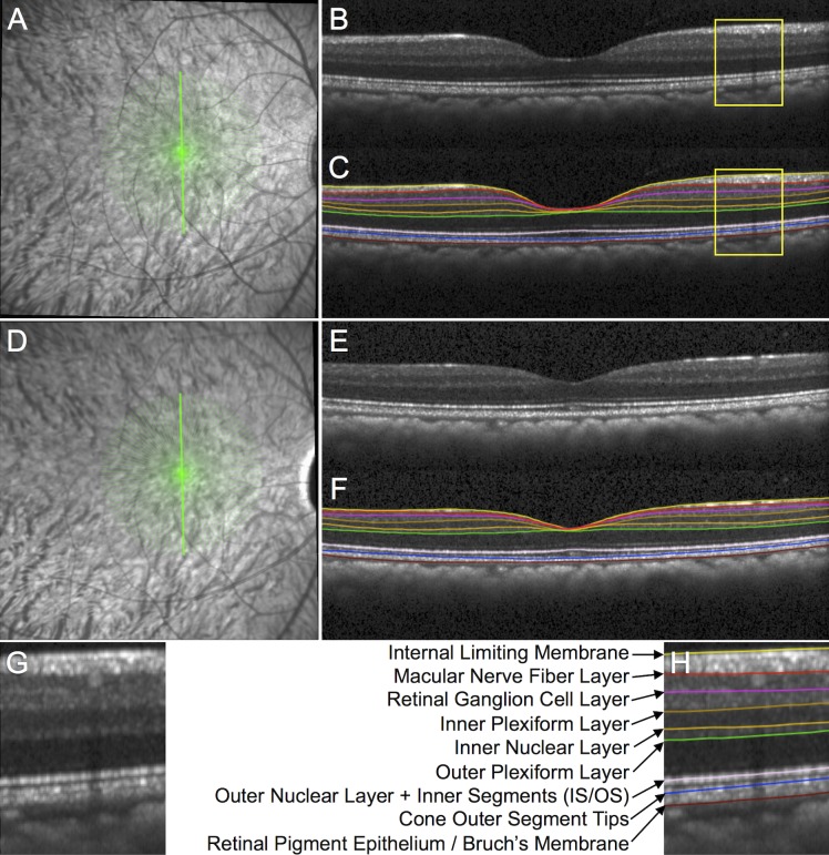
Figure 2.
Spectral-domain OCT B-scan image segmentation to measure macular layer thicknesses. (A) The SDOCT radial 15° B-scan pattern is shown by the 48 green lines overlaid onto the infrared reflectance image at baseline in an individual EG eye. (B) Example of a single B-scan without segmentation and (C) with segmentation from the location indicated by the bold green vertically oriented spoke in (A). (D) Infrared reflectance image in the same EG eye at its final follow-up. (E) Vertical B-scan obtained at the final follow-up from the same location without segmentation and (F) with segmentation. (G) Magnified portion of the baseline B-scan from the inset indicated by the yellow box in (B) without segmentation and (H) with segmentation. The features segmented in each B-scan included the ILM and the posterior boundary of the following: m-NFL, RGCL, IPL, INL, OPL, and retinal pigment epithelium (Bruch's membrane). The center the reflectance bands associated with the IS/OS junction and the COST were also segmented, which served as the posterior boundaries of the combined outer nuclear layer + photoreceptor inner segments and the photoreceptor outer segments, respectively.21

