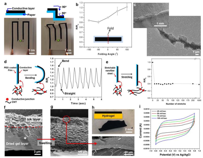
Figure 2. Electrical characteristics on flexible substrates during deformation.
(a) Operation of a LED connected by ink circuits screen-printed on a cellulose paper substrate before and after folding. (b) Relative resistance change of the screen printed ink circuits fabricated on cellulose paper substrates and folded under various curvature angles. The inset is a schematic diagram of the ink circuit used for the measurement (Length × width = 5 cm × 1 cm). (c) SEM image of ink circuits on cellulose paper substrates after folding (180o). (d) Schematic diagram and the change in relative resistance after dynamic and cyclic bending deformation of the screen printed ink circuit on a PEG coated PET film. (e) Schematic diagram and relative resistance change as a function of elongation for ink circuits on stretchable PGS/PCL substrate (ε = 0.2 tensile strain). (f and g) Representative SEM images showing cross-section of the ink covered 7% GelMA hydrogel (Double layer) (f) before and (g) after swelling in PBS. (h) Photographs showing ink covered GelMA hydrogels after swelling in PBS. (i) Cyclic voltammetry of the ink coated 7% GelMA hydrogel in PBS.

