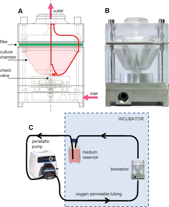
Fig 1. Dynamic suspension bioreactor.
(A) Schematic draw of the bioreactor showing its internal components and its axial symmetry (red lines). (B) Picture of the bioreactor. (C) Schematic representation of the set-up of the bioreactor connected to the closed loop recirculation circuit and positioned within the incubator.

