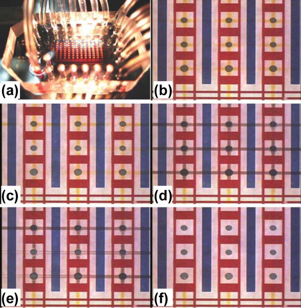
Figure 19.

(a) Photo of SPR imaging integrated with a microfluidic system. (b)–(f) Consecutive photos of the SPR imaging chip that is carrying out immunoreactions in the microfluidic system. (b) Vertical reagent injection step: a reagent (yellow liquid) is injected into the flow channels and then delivered to the Au spots. (c) First rinse step: a washing buffer (clear liquid) is injected to rinse the Au spots. (d) Horizontal reagent injection step: a reagent (black liquid) is injected into the flow channels then delivered to the Au spots. (e) Second rinse step: a washing buffer (clear liquid) is injected to rinse the Au spots. (f) The channels in the microfluidic device are clear after the second rinse. Reprinted with permission from ref. 168. Copyright (2008) Royal Society of Chemistry.
