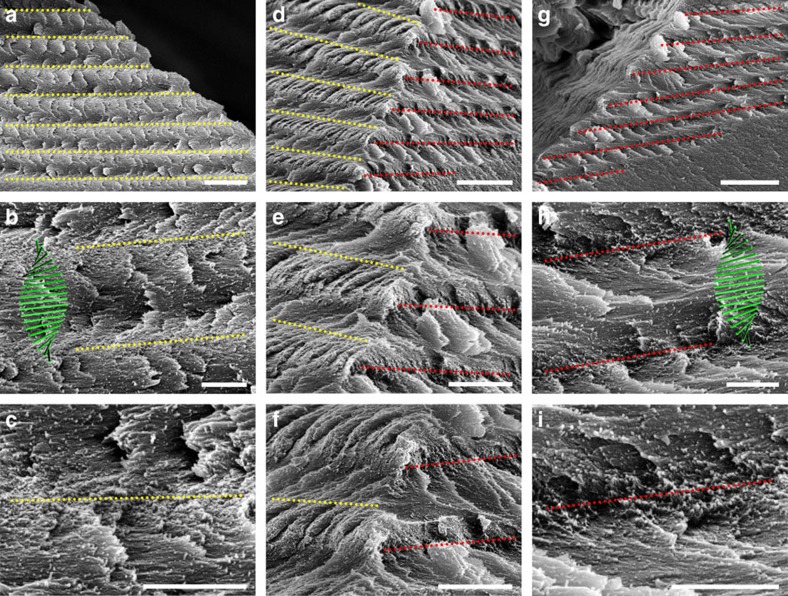
Figure 5. The three dimensional spatial structure of a tactoid.
The tactoid shown in Fig. 4 is examined by SEM from different directions. Left, front and right views are placed in the left, middle, and right columns, respectively. On the left side, CNCs perpendicular to the cross-section (the CNCs projecting out) are indicated by yellow lines (c), while at the right side they are indicated by red lines (i). The region between two adjacent lines is a half helical pitch as shown in b and h, while the long-range spacing is depicted in a and g. From d–f we can see that the CNCs projecting out on the left and right sides of the tactoid are alternately arranged, which is a solid confirmation of the chiral nematic ordering in CNC tactoids. Scale bars, (a) 5 μm, (b,c) 1 μm, (d) 5 μm, (e,f) 2 μm, (g) 5 μm and (h,i) 1 μm.

