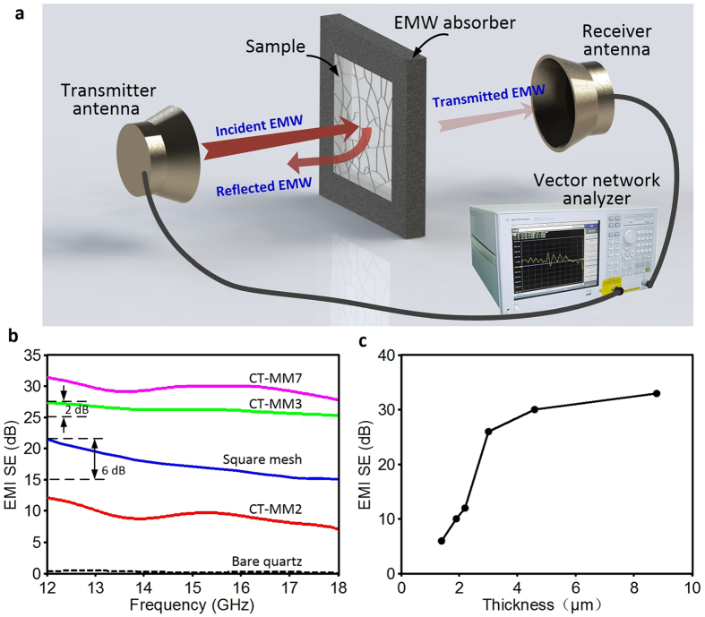
Figure 5. Microwave shielding performances of CT-MM films and the testing schematic.
(a) Schematic illustration of the EMI shielding measurement setup. The sample was installed in a centre-hollowed EMW absorber (foam, 500 × 500 × 5 mm3). (b) EMI SE of CT-MM films measured in the frequency range of 12–18 GHz. (c) EMI SE at a frequency of 18 GHz of CT-MM films fabricated by CE3 with different thicknesses.

