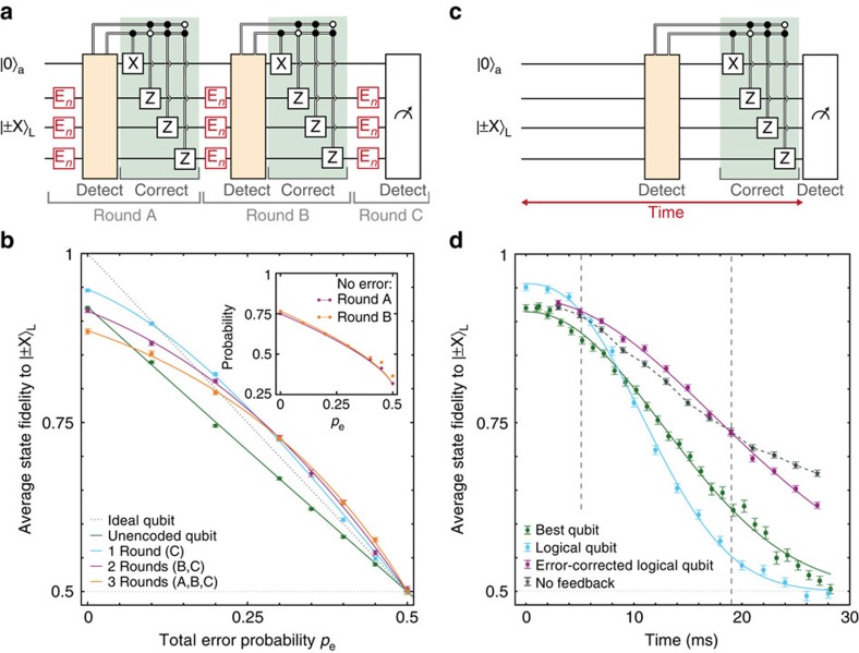
Figure 4. Extending coherence by active quantum error correction.
(a) Three rounds of error correction on a logical qubit. The first two rounds of quantum error correction use stabilizer measurements and feedback. The final round is implemented by majority voting. (b) Average logical state fidelity for  and
and  as a function of total error probability pe for n=1, 2 and 3 rounds of error correction compared with an unencoded qubit. The errors per round En occur with probability pn. Inset: probabilities that no error is detected (n=3). The similarity of the results for rounds A and B confirms that errors are corrected in between rounds. (c) Correcting natural dephasing. The storage time is defined from the end of the encoding until the start of the final measurements. (d) Dephasing of the logical qubit: without stabilizer measurements, with quantum error correction and without feedback, compared with the best unencoded qubit. The dashed lines indicate the times between which the actively error-corrected logical qubit gives the highest fidelity. The data without feedback (detecting errors without correcting) isolate the suppression of coherently evolving errors by projecting them. For long times, applying error correction lowers the fidelity because the stabilizer measurements extract no useful information about errors, but nevertheless preferentially suppress evolutions that result in phase errors at the end of the sequence (see Supplementary Fig. 10 for a detailed analysis). See Supplementary Fig. 9 for error syndrome probabilities. Solid curves in b,d are fits described in the Methods and Supplementary Notes 1 and 2. Dashed lines are a guide to the eye. All error bars are one statistical s.d.

