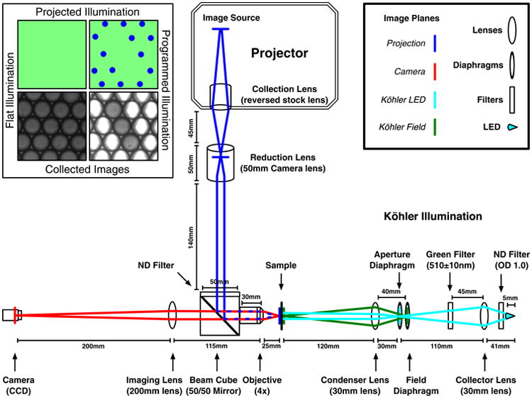
Fig. 1.

Schematic of the Programmable Illumination Microscope (PIM) optics. It consists of a commercial projector with inverted optics that projects blue light onto the sample, which is illuminated by green Köhler illumination on the right arm. Images are taken by a CCD on the left arm. The top-right inset is a legend for the optical components and image planes. The top-left inset demonstrates the projected illumination and collected images from the PIM. Within the inset the top-left is an illustration of the flat green illumination and bottom-left is an image of the emulsion collected with flat illumination, the top-right is an illustration of programmed illumination and bottom-right is an optically isolated NOR gate. The outer two droplets of the NOR gate are the inputs and the central droplet of the NOR gate is the output.
