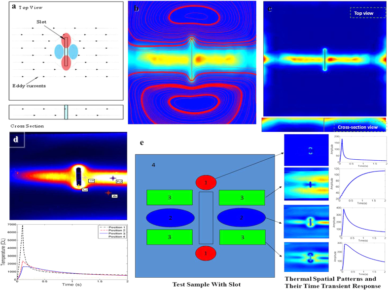
Figure 2. Illustration of Thermal- Electromagnetic patterns.
(a) Schematic of theoretical EC distribution and resultant heating for slot. (b) Simulation of fused EC and heat distribution. (c) Simulation of heat. (d) Real test sample and its thermal spatial-transient signal. (e) Spatial-Transient pattern interpretation and separation results.

