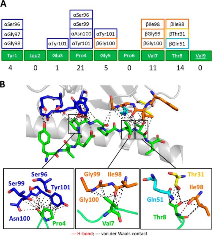
FIGURE 4.

The PMEL17 CDR loops focus on peptide residues Pro4, Val7, and Thr8. A, schematic representation of contacts between YLE-9V peptide and PMEL17 CDR loop residues (color-coded as in Fig. 2A). The numbers at the bottom show total contacts between the TCR and peptide. B, contacts between the PMEL17 TCR and the YLE-9V peptide (green sticks), showing the van der Waals contacts (black dashed lines) and hydrogen bonds (red dashed lines) made by the TCR CDR3α (blue), CDR1β (yellow), CDR2β (aqua), and CDR3β (orange) loops. Bottom panel, close view of contacts between YLE Pro4, Val7, and Thr8, respectively, and TCR CDR loop residues (sticks color-coded as in Fig. 1A) (cut-off of 3.4 Å for hydrogen bonds and a cut-off of 4 Å for van der Waals contacts).
