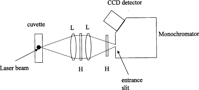
Fig. 1.
A schematic diagram of the apparatus used to measure the fluorescence intensity from a solution (suspension) in a cuvette or a flow thru cell. The laser beam is coming out of the plane of the figure and is represented by the dot in the cuvette. The pair of lenses (L) focus the illuminated region in the cuvette on the monochromator entrance slit (M=1). The holographic notch filters (H) are tuned to reject the laser radiation wavelength, in this case 488 nm. The entrance slit is imaged and dispersed on the CCD detector.

