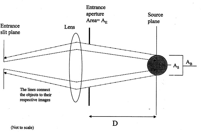
Fig. 4.
A schematic diagram of the geometry that is used to convert a volume fluorescence source into a equivalent surface source. AB is the cross sectional area of the illuminating laser beam which is coming out of the plane of the figure. The source plane intersects the illuminating beam at its mid section. AE is the area of the entrance aperture of the collecting optics, and D is the distance between the entrance aperture and the source plane. Finally, AS is the area of the image of the monochromator entrance slit on the source plane. (AS < AB). The refraction at the cuvette wall is not shown in the figure. A radiance standard would replace the cuvette during calibration. The surface of the radiance standard is placed at the source plane.

