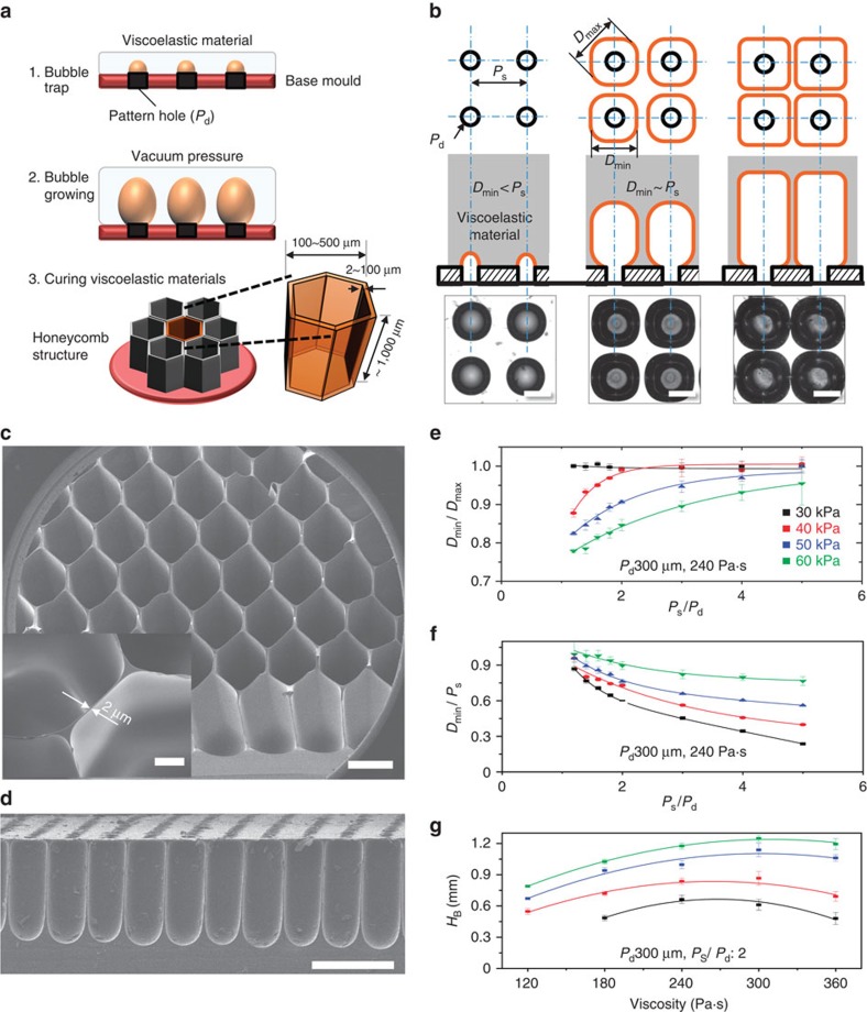
Figure 1. The principles underlying viscoelastic lithography.
(a) The fabrication of tunable honeycomb microstructures using viscoelastic lithography. (b) Growth and interactions among bubbles in the HV-PDMS under a negative pressure (20 to 70 kPa below atmospheric pressure). The trapped air slowly increased in volume to form spherical bubbles in the HV-PDMS matrix (isotropic expansion phase). Polygonal bubbles were formed as the bubbles interacted with neighbouring bubbles (anisotropic expansion phase). The scale bar, 300 μm. (c) SEM image of the micro-honeycomb structures fabricated using viscoelastic lithography. The minimum wall thickness was 2 μm (inset, scale bar, 100 μm), and the aspect ratio was ∼500 (height to wall thickness). The scale bar, 500 μm. (d) Cross-sectional image of the micro-honeycomb structure. The scale bar, 500 μm. (e,f) The relationship between the polygonal factor Dmin/Dmax and the pattern parameters over a range of pressures. Small separation distances between bubbles gave Dmin/Dmax values approaching 1. (g) The height of the bubble as a function of the HV-PDMS properties over a range of pressure (30−60 kPa below atmospheric pressure). The bubble height in the HV-PDMS gradually increased, although it decreased under higher viscosity conditions (360 Pa·s). All error bars indicate the s.d.'s.

