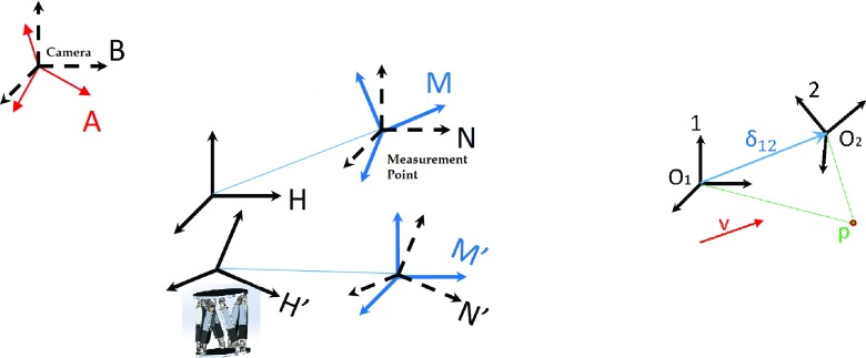
FIG. 2.
The assembly of coordinate systems considered for motion control, calibration and tracking evaluation (left), and the point and vector representation in two coordinate frames (right). Here, coordinate frames A and B are the camera frames, M and N are the measurement coordinate frames, H is the control frame for the phantom, and the primed analogs are these latter coordinate frames after motions were performed by the H control frame.

