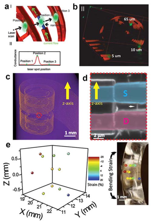
Figure 28.
(a) Schematic of 3D macroporous NW structure highlighting simultaneous confocal fluorescence and photocurrent imaging to localize the positions of NW FET devices: blue cylinder, NW; orange-red, polymer mesh network; green dot, laser spot. (b) 3D reconstructed confocal fluorescence/photocurrent microscopy image of a 3D mesh structure. The polymer mesh structure is red-orange and NW FET positions are green. (c) 3D micro-CT image of a strain sensor array embedded in an elastomer, where metal interconnects are visible as yellow-orange lines. (d) Optical image of a typical NW device. The white arrow points to the NW, and source (S) and drain (D) highlighted with blue and pink coloring, respectively. (e) 3D strain field mapped by the NW strain sensors, left; and image of elastomer with embedded macroporous NW network, right. Reprinted with permission from Ref. 22. Copyright 2013 National Academy of Sciences of the United States of America.

