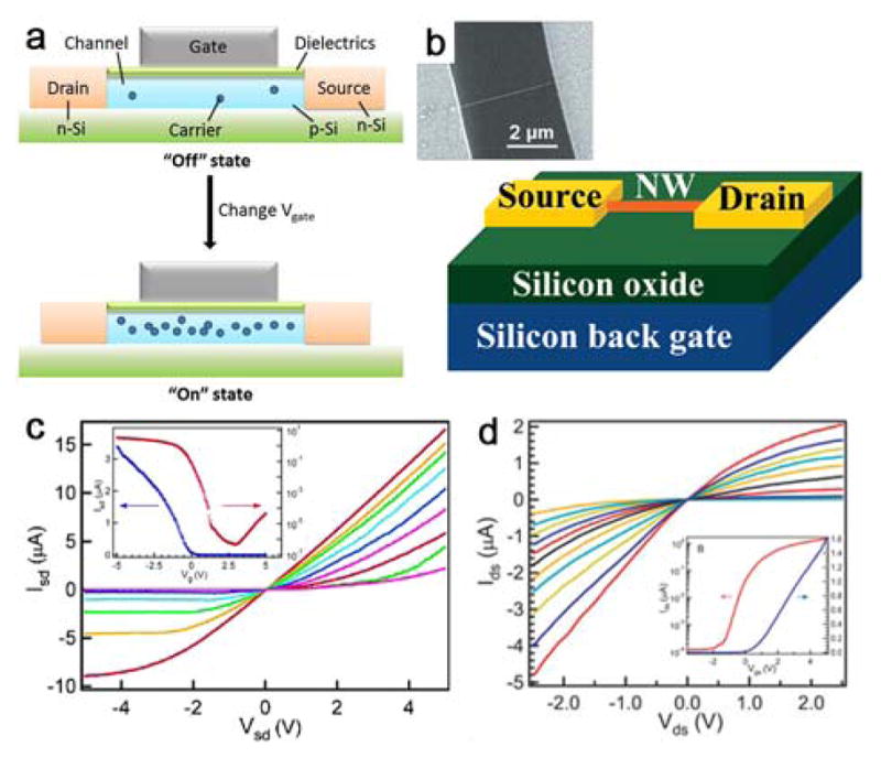
Figure 5.

(a) A typical planar FET. The semiconductor substrate (e.g., p-Si) is connected to gate (G), source (S) and drain (D) electrodes, and can be switches between the “off” and “on” states by applying the Vg. (b) Schematic and SEM image of a NW-FET. Reprinted with permission from Ref. 175. Copyright 2002 American Chemical Society. (c, d) Transistor characteristics of p- and n-type NWs. Insets show transfer characteristics of the back-gated devices. (c) Reprinted with permission from Ref. 135. Copyright 2004 American Chemical Society. (d) Reprinted with permission from Ref. 179. Copyright 2004 John Wiley & Sons, Inc.
