Abstract
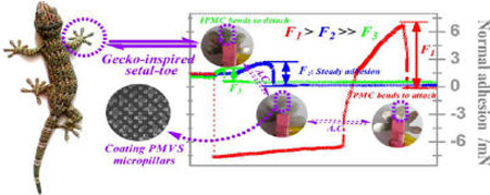
Inspired by how geckos abduct, rotate, and adduct their setal foot toes to adhere to different surfaces, we have developed an artificial muscle material called ion-exchange polymer–metal composite (IPMC), which, as a synthetic adhesive, is capable of changing its adhesion properties. The synthetic adhesive was cast from a Si template through a sticky colloid precursor of poly(methylvinylsiloxane) (PMVS). The PMVS array of setal micropillars had a high density of pillars (3.8 × 10³ pillars/mm2) with a mean diameter of 3 µm and a pore thickness of 10 µm. A graphene oxide monolayer containing Ag globular nanoparticles (GO/Ag NPs) with diameters of 5–30 nm was fabricated and doped in an ion-exchanging Nafion membrane to improve its carrier transfer, water-saving, and ion-exchange capabilities, which thus enhanced the electromechanical response of IPMC. After being attached to PMVS micropillars, IPMC was actuated by square wave inputs at 1.0, 1.5, or 2.0 V to bend back and forth, driving the micropillars to actively grip or release the surface. To determine the adhesion of the micropillars, the normal adsorption and desorption forces were measured as the IPMC drives the setal micropillars to grip and release, respectively. Adhesion results demonstrated that the normal adsorption forces were 5.54-, 14.20-, and 23.13-fold higher than the normal desorption forces under 1.0, 1.5, or 2.0 V, respectively. In addition, shear adhesion or friction increased by 98, 219, and 245%, respectively. Our new technique provides advanced design strategies for reversible gecko-inspired synthetic adhesives, which might be used for spiderman-like wall-climbing devices with unprecedented performance.
Keywords: synthetic adhesive, adhesion, friction, setal micropillar, ion-exchange polymer–metal composite (IPMC), poly(methylvinylsiloxane) (PMVS)
Graphical abstract
1. INTRODUCTION
Gecko toe pads possess a robust, reversible adhesion mechanism that allows them to freely move on surfaces of any texture (rough or smooth) and orientation (horizontal, vertical, or inverted).1–4 Movement occurs at high speed (up to ~1.5 m/s), even when loaded with heavy telecommunication equipment.5 This fascinating motion capability is thought to be derived from the unique structure of the gecko’s toes, where numerous mesoscale setae grow. Therefore, the gecko’s toe pad structure has become a model for developing wall-climbing robots.6–8 Most setae are approximately 130 µm long and 5 µm in diameter. Each seta branches out to hundreds of microscale spatula-ended pillars.9,10 These micropillars thus ensure maximal contact with the surface, resulting in a reversible, strong attractive force based on substantial van der Waals interactions and/or capillary interactions under humid conditions.11
These unique structures have stimulated the development of fabrication techniques for bioinspired micro/nanoarrays. Mimetic setal structures have become an interdisciplinary research area that combines materials, bionics, mechanics, nanotechnology, and many other fields.12,13 Existing micro/nanoarrays exhibit fascinating properties such as adhesion, hydrophobicity, and self-cleaning.14–18 However, when compared to natural gecko foot toes, the development of next-generation synthetic adhesives that are highly mimetic and practicable has been hindered by several challenges, including the following: (1) The natural gecko’s setae are driven by muscle (Figure 1). The contact area may be tailored by the normal pressure loaded by the supporting muscle to increase or decrease the adhesion. Such muscle-controlled adhesion is important and explains why the adhesion of toes from a live gecko is far greater than that of dissected toes as well as why setae adhesion of nonanesthetized geckos is significantly different from that of anesthetized ones. (2) Geckos employ various muscle-driven motions such as abduction, rotation, and adduction to meet the needs of attachment to or detachment from different surfaces.19 (3) Gecko’s foot toes remain relatively clean even after long-distance travel; dirt is easily removed by interstitial friction among setae, which is a self-cleaning property.20,21 (4) Lastly, although synthetic adhesives present extraordinary adhesion capability, switching between detachment and attachment is very challenging.
Figure 1.
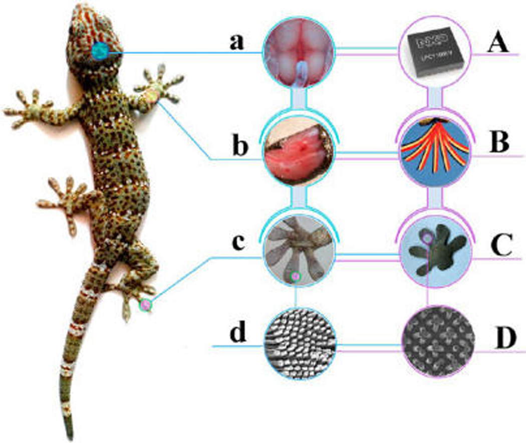
Schematic illustration showing the biomimetic approach of synthetic foot toes inspired by the hierarchical design of a gecko’s toes. (a) The brain of a natural gecko, which sends out bioelectric signals to muscle tissue; (b) foreleg muscle, which controls the ability of the forefoot toes to abduct, rotate, and adduct; (c) forefeet toes, on which millions of setae grow; (d) scanning electron microscopy (SEM) image of setae. A–D demonstrate the biomimetic targets correlated to those shown in a–d, respectively. (A) Signal-generating chip that sends out an electric signal to drive the IPMC to be back and forth. (B) Multiple images are overlaid to show continuous actuations of the IPMC actuator (shown in dark black) attached to a thick PDMS membrane (shown in light red), with a thickness of around 2 mm. The IPMC membrane is actuated by a sinusoidal wave with a frequency of 0.1 Hz under a voltage of 3.0 V. (C) Synthetic gecko-inspired foot toes made of PMVS micropillars attached to IPMC. (D) SEM image of PMVS micropillars.
Artificial simulation of muscle control would be beneficial in mimicking the gecko’s ability to modulate adhesive forces. The del Campo and Greiner groups employed temperature and magnetic field, respectively, to switch the adhesion of setal microarrays.22–25 Herein, we have developed gecko-inspired toes constructed of a polymer micropillar array, which is controlled by an electro-active polymer (EAP) called ion-exchange polymer–metal composite (IPMC)26–30 (Figure 1). To produce strong van der Waals interactions, a sticky colloid precursor of poly(methylvinylsiloxane) (PMVS) was used to cast the negative Si template obtained with Ar+ plasma etching, yielding PMVS-based setal micropillars. Because PMVS micropillars are highly compliant and because IPMC is a flexible actuator, IPMC is able to drive PMVS setal pillars to perfectly match the opposing surface.
As a new type of E-active artificial muscle, IPMC has a wide range of applications. Its advantages include producing a large displacement output under a very low driving voltage.26 Its working mechanisms have been associated with the well-known armwrestling match between an EAP-actuated robotic arm and a human. For a conventional IPMC actuator, an ion-exchange membrane, such as Nafion or Flemion, is sandwiched between two inert metal (i.e., Pt) sheets that function as electrodes. To enhance its carrier transfer, water-saving, and ion-exchange capabilities, a graphene oxide (GO) monolayer containing Ag nanoparticles (GO/Ag NPs) was fabricated and doped into a commercial Nafion solution to improve the electromechanical response of the IPMC.31 After transferring PMVS micropillars onto the IPMC surface, the IPMC is actuated by alternating current, causing bending oscillations by the PMVS micropillars. Therefore, the blocking force generated from the IPMC can be used as a normal pressure to actively drive the PMVS setal micropillars to adhere to or detach from a surface, mimicking gecko muscle. Positive pressure drives micropillars into the opposing surface, similar to muscle adduction for attachment, whereas negative pressure pushes micropillars away from the opposing surface, similar to abduction for detachment.
2. EXPERIMENTAL SECTION
2.1. Materials
Nafion-115 (perfluorosulfonic acid-co-polytetrafluoroethylene, 20%) was obtained from Dupont Company (USA). Poly(dimethylsiloxane) (PDMS, Sylgard 186) was from Dow Corning (Midland, MI, USA). PMVS colloid derived from PDMS precursor with a mass ratio of 1:20 (A/B) was used to cast setal micropillars, and poly(methylhydrosiloxane) (PMHS) colloid derived from PDMS precursor with a mass ratio of 1:5 (A/B) was used to bind the setal micropillars to IPMC (Supporting Information, S1). Natural flake graphite (NFG, 80 meshes) was obtained from Nanjing XFNano Materials Tech Co., Ltd. (Nanjing, China). Pt(NH3)4Cl2 and AgNO3 were obtained from Sigma-Aldrich Inc. (St. Louis, MO, USA). Deionized water with a resistivity of 18.2 MΩ (Millipore, Purification System) was used to prepare the related solution.
2.2. Fabrication of GO/Ag NP-Doped IPMC
GO/Ag NPs and pure Nafion membranes were used to fabricate IPMC actuators. Briefly, Nafion membranes were polished by a grinder polisher. The polished membranes were then immersed into the Pt(II) solution for ion exchange. The adsorbed Pt(II) ions were reduced by the addition of sodium borohydride. The Pt(0) nanograins were sandwiched between the membrane’s surfaces and then plated by reduction of hydrazine (NH2–NH2) in a Pt(II) solution, which adsorbed fine Pt(0) nanograins onto both surfaces. After a secondary plating, the IPMC samples were washed and incubated in a LiOH (0.05 mol/L) solution. Both IPMC samples underwent low-temperature cracking for FESEM observations. Procedures for preparing the GO/Ag NPs and the hybrid Nafion membrane are recorded in the Supporting Information (S2–S3). Measurement of the relative ion-exchange capabilities of the membranes was also recorded (Supporting Information, S4).
2.3. Molding PMVS Setal Micropillars in Vacuum
Negative pores on the Si template, with an average diameter of 3 µm and depth of 10 µm, were prepared by Ar plasma etching (Alcatel 601E, France) using p-type (100)-oriented crystal Si as the matrix (Supporting Information, S5). As shown in Figure 2, the Si template was put into containers with the PMVS colloid. Containers were then placed in a vacuum desiccator (Figure 2a). After 10 min under vacuum (Edwards RV5, England), the Si template was inserted into the PMVS colloid. Vacuum was subsequently released, and atmospheric pressure drove the PMVS colloid into the Si template (Figure 2b). After vulcanization, excess PMVS elastomer was removed by plasma etching (Figure 2c,d). The sample was placed onto a thin PMHS (1:5) membrane and vulcanized for 0.5 h at 80 °C, thus covalently bonding PMVS to the PMHS membrane (Figures 2e–g). The crystal Si template was etched away, yielding an array of PMVS-based setal micropillars (Figures 2g,h). Finally, Pt particles (~5 nm) were deposited to produce a defined electroconductivity. The Si-negative template and the resultant PMVS setal micropillars were observed by SEM (JSM-7001F).
Figure 2.

Schematic illustration of the fabrication process for the IPMC-based membrane with an array of PMVS micropillars. Demolding courses of PMVS setal micropillars (a–h) and adhering IPMC courses (h–j).
2.4. Fabrication of an IPMC Membrane Carrying an Array of PMVS Micropillars
This composite membrane consisted of four layers (Figure 2): a PMVS micropillar layer, PMHS binder layer, PMVS binder layer, and IPMC substrate layer. Through a hydrosilylation reaction between the Si–H group in the PMHS prepolymer and the C=C group in the PMVS prepolymer, the three top layers were covalently cross-linked. As PDMS is highly adhesive to metals, the IPMC substrate with Pt nanograins was tightly bonded to the PMVS–PMHS membrane (Figures 2h–j). To avoid possible diffusion of PDMS colloids into the IPMC, which may block the microchannels inside the Nafion membrane, vulcanization should be initiated immediately after fabricating the IPMC membrane. Because the top three layers of the PDMS-derived membrane are transparent, ultrathin (≤150 µm), and thus difficult to image, an additional layer of colored PDMS membrane with a thickness of ~2 mm was attached to the IPMC surface to facilitate imaging the motion of the PMVS micropillars driven by the IPMC. The images were captured by a high-speed camera (Olympus, LT) with a fixed speed of 250 frames per second.
2.5. Setup for IPMC Actuator Performance Measurements
A signal generator (SP1651, Nanjing, China) with a multifunction data collection card (NI, 6024E) and a signal amplifier (TI, OPA548) was used to generate a two-way square wave with varying voltages of 1.0–2.0 V and a fixed frequency of 0.1 Hz for IPMC actuation (Supporting Information, S6). Blocking forces were collected from a micronewton force sensor (CETR-UMT), and electric current forces were collected from a Hall electric current sensor (TBC-A02). A high-speed video camera (Olympus, LT) captured images of the setae swing angles.
2.6. Measuring Adhesion of PMVS Micropillars Triggered by the IPMC Actuator
Adhesion measurements in both the normal and shear directions took four steps. In the preloading step, the sapphire ball approached the sample with a fixed speed of 50 µm/s and stopped when the normal preload reached 0.01 mN. The IPMC was actuated by a continuous current for 10 s. The electrode on the sapphire ball side was set as the anode. The IPMC membrane carrying the PMVS micropillars bent to the sapphire ball, and the blocking forces were used as preloads. In the off-loading step, the IPMC stopped actuation for 5 s, and the sample was attached to the sapphire ball through adhesive forces. To determine the normal adhesion (Figure 3a), the sapphire ball was lifted continually at a fixed rate of 2.5 mm/s. Meanwhile, the IPMC was actuated by continuous current with a voltage of 1.0, 1.5, or 2.0 V. An electrode on the sapphire ball side was set as the anode or cathode, resulting in the IPMC bending toward or away from the sapphire ball, respectively. To determine the shear adhesion (Figure 3b), in the following sliding step, the sapphire ball was mounted to slide along the x axis of the PMVS micropillars at a constant rate of 25 µm/s for 10 s. Meanwhile, the IPMC was actuated by continuous current under a voltage of 1.0, 1.5, or 2.0 V. The electrode on the sapphire ball side was set as the anode. As a control, steady adhesions (when the IPMC stopped working), including the normal and shear adhesions, were also collected. In the unloading step, the sapphire ball was lifted at a fixed rate of 2.5 mm/s and departed from the micropillar-patterned IPMC surface.
Figure 3.
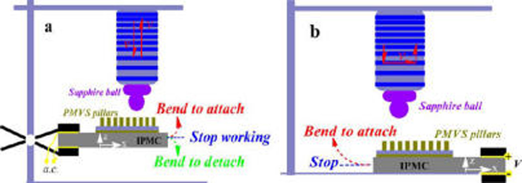
Schematic illustration for detecting normal (a) and shear (b) adhesions. A rigid sapphire ball was fixed at the end of force sensor to act as the upper mating ball, and the IPMC membrane carrying an array of PMVS micropillars was used as the sample. The IPMC was auctated by a low voltage of 1.0, 1.5, or 2.0 V.
3. RESULTS AND DISCUSSION
3.1. SEM Images of the PMVS Setal Micropillars
Figure 4a shows a three-dimensional morphology of the PMVS setal micropillars with a density of ~3.8 × 10³ setae/mm2. Each pillar exhibits a well-defined columnar structure with a smooth end tip and a mean diameter of 3 µm (Figure 4b). A comparison of the PMVS setal micropillar SEM images with those of the negative pores (Supporting Information, S5), where the pore diameter is 3 µm, the pitch is around 1.2 µm, and pore thickness is around 10 µm, indicates that the resultant micropillar should have an aspect ratio of ~3.3, which is slightly lower than the collapse limit of 3.5 for PDMS-based setae.32,33 It should be noted that micropillars with high density and high aspect ratio easily collapse, thus weakening the adhesion performance. After multiple adhesion tests, micropillars could be heavily deformed, clustering together to decrease the adhesion.34,35 Therefore, the micropillar design was optimized for cost effectiveness and performance repeatability, thereby ensuring accurate evaluation of adhesion modulation. Collectively, the SEM images (Figure 4) show a perfect match between the patterns in the setal micropillar array and the negative template, demonstrating successful replication.
Figure 4.
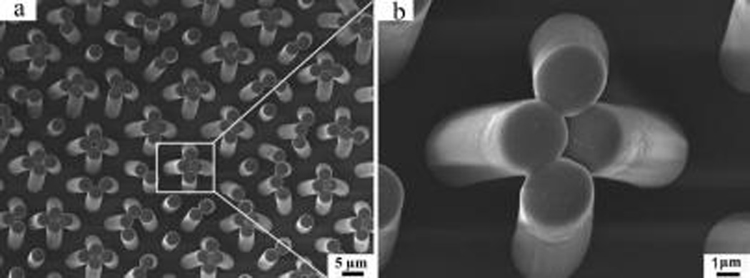
Top-view SEM image of PMVS setal micropillars (a) and its magnified image (b).
3.2. High-Resolution Transmission Electron Microscopy (HRTEM) Images of GO and GO/Ag NPs
Figure 5a shows a TEM image of the GO monolayer with a flexible sheet structure and small wrinkles on the surface. Because of the large number of O-containing groups, the GO monolayer is highly hydrophilic and polarized36–38 and is compatible with the polar Nafion solution. The HRTEM image shows that there are 8–13 layers of GO sheets stacking at the edge (Figure 5b). The TEM image of GO/Ag NPs (Figure 5c) demonstrates that, after the reduction of glucose and change of Ag+ into Ag NPs (Supporting Information, S2), most Ag NPs have a spherical morphology with a diameter varying from 5 to 30 nm. Small wrinkles in the GO monolayer are scattered among the Ag NPs, showing their attachment onto the surface of the GO monolayer. The HRTEM image further illustrates the polycrystalline structure of the Ag NPs, whose lattice pitch is around 0.22 nm (Figure 5d).
Figure 5.
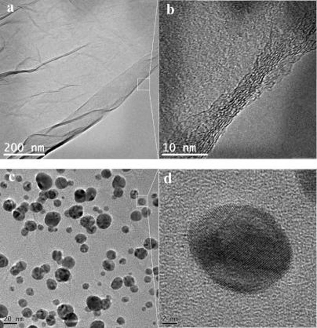
TEM (a, c) and HRTEM (b, d) images of GO (a, b) and GO/Ag NPs (c, d).
3.3. Field Emission SEM (FESEM) Images of the IPMC with GO/Ag NPs
Figure 6a shows the cross-sectional morphology of the IPMC, which was produced by sandwiching the GO/Ag NP-doped Nafion membrane between two Pt nanograin sheets. The thicknesses of the hybrid polymer membrane and the electrode layer are approximately 216 and 5.0 µm, respectively. Due to differences in their electrical conductivity, a distinct interface occurred between the layers. The bottom fracture surface presents a typical plastic fracture pattern, whereas the upper fracture surface presents a ductile, dimpled fracture pattern, probably caused by stress differences when cracking at low temperature. To further characterize the doping of the GO/Ag NPs, the dimpled fracture texture was magnified. Figure 6b shows alternating light and shaded regions, suggesting that GO monolayers are homogeneously dispersed inside the Nafion membrane. With higher magnification, numerous microscale channels and holes were visible (Figure 6c), which may hold a great quantity of water and provide channels through which hydrated cations can migrate, thus enhancing the electromechanical responses of the IPMC.28 With the Nafion coating, most of the GO/Ag NPs exhibit amorphous morphology; isolated Ag NPs with varying diameters (10–50 nm) homogeneously disperse inside the Nafion membrane. Both GO/Ag NPs and isolated Ag NPs contribute to the conductivity of the hybrid membrane.
Figure 6.
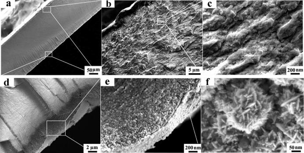
SEM images of the IPMC. After freeze cracking in liquid N2, samples were deposited with Pt particles (~5 nm) for SEM imaging. (a) Cross-sectional image of the IPMC at a magnification of 200×. The two surfaces are sandwiched between two layers of Pt nanosheets. (b, c) Cross-sectional image of the hybrid membrane with magnifications of 3000× (b) and 50 000× (c). (d, e) Pt nanosheet with magnifications of 5000× (d) and 50 000× (e). (f) Top-view image of Pt nanograins with a magnification of 200 000×.
Figure 6d–f shows the detailed structure of Pt nanograin sheets, which are used as electrodes for the E-active polymer. The Pt nanograin derives from the reduction of the Pt(II) cation adsorbed inside the Nafion membrane during the primary plating step. Pt(II) acts as the courter cation to the sulfonic anion. Figure 6d presents an image of a Pt nanosheet with a mean thickness of 4.8 µm, which closely binds with the polymer membrane. Figure 6e further shows that this Pt sheet is mainly made of numerous Pt nanograins with varying diameters (10–80 nm). Along the normal direction, there is a concentration gradient of Pt nanograins. The top layer is mainly pure Pt nanograin, followed by a mixture of Pt nanograins and Nafion polymer. Embedding Pt nanograins in Nafion polymer prevents the separation of Pt from the Nafion surface and thus ensures a stable electromechanical response.27 Figure 6f shows the top view of the Pt nanograins, which consist of numerous layered nanocrystallites, with a mean diameter of ~8 nm and varying lengths (30–120 nm). The nanocrystallites are probably formed during the process of secondary plating, which fills in the cracks in the Pt sheets, thus improving surface conductivity.
3.4. Electromechanical Properties
For an E-active actuator, generating electrical signals is a critical function. Figure 7a and Table 1 demonstrate the electric current through the IPMC, which derives from the migration of hydrogen cations between two electrodes. Clearly, when actuated by a two-way square wave, the electric current quickly reaches a maximal value when the electrode’s polarity reverses and is followed by a sudden drop and then a gradual decrease. Under actuation voltages of 1.0, 1.5, and 2.0 V, the peak currents for the hybrid membrane are 91, 81, and 72 mA, respectively, and those for the pure self-casting Nafion membrane are 61, 54, and 47 mA, respectively. Since the swing of the IPMC might derive from the “granular damming effect”,39,40 in which the Pt nanograin electrode blocks the migration of the inner hydrate cations, the hybrid membrane with a higher carrier-transfer capability shows a better electromechanical response.
Figure 7.
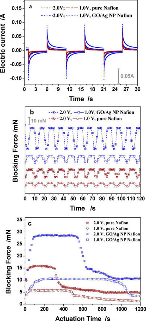
Electromechanical properties of the IPMC actuators made from the pure Nafion membrane (curves in deep-red color) and GO/Ag NP-doped Nafion membrane (curves in blue color). (a) Representative electric signals collected from the Hall electric current sensor; (b) representative blocking force curves collected from the force sensor; (c) relationship between the blocking force and the actuation time. The IPMC was actuated by a square-wave voltage with a mean of 1.0 or 2.0 V and a fixed frequency of 0.1 Hz.
Table 1.
Comparison of the Electromechanical Properties and Other Related Properties for Both Actuators
| actuator | thickness (µm) |
ion-exchange capability (mMol/g) |
peak electric current (mA) |
mean swing angle (deg) |
max. blocking force (mN) |
stable actuation time (s) |
||||||||
|---|---|---|---|---|---|---|---|---|---|---|---|---|---|---|
| 2.0 V | 1.5 V | 1.0 V | 2.0 V | 1.5 V | 1.0 V | 2.0 V | 1.5 V | 1.0 V | 2.0 V | 1.5 V | 1.0 V | |||
| pure Nafion | 192 | 0.42 | 61 | 54 | 47 | 51 | 42 | 36 | 15.9 | 9.50 | 7.20 | 270 | 395 | 450 |
| hybrid Nafion | 216 | 0.61 | 91 | 81 | 72 | 63 | 49 | 38 | 29.3 | 15.6 | 10.6 | 520 | 620 | 840 |
The blocking force generated from IPMC bending, another important parameter, was evaluated by a millinewton level force sensor (Supporting Information, S6). For the hybrid Nafion IPMC and pure Nafion IPMC, their respective blocking forces are 10.6 and 7.20 mN under 1.0 V, 15.6 and 9.50 mN under 1.5 V, and 29.3 and 15.9 mN under 2.0 V (Figure 7b and Table 1). We thus conclude that (1) compared with the pure Nafion IPMC, the hybrid Nafion IPMC produced a higher force output, which is consistent with the results of electric current, and (2) there is a direct correlation between blocking force and driving voltage, suggesting a simple method of controlling blocking voltage. Because the maximal blocking force is contributed by the migration of total hydrate cations, the position of the peak force lags behind the peak current (Figures 7a,b).
Additional evidence showing the improved performance is demonstrated by the stable actuation time (SAT) in air. With continuous actuation, the blocking force attenuates because of water loss. Therefore, water replenishment is needed to recover the electromechanical response. Figure 7c shows that all four curves exhibit an initial rise followed by a relatively stable force output that corresponds to the SAT for the actuator. As shown in Table 1, for the pure Nafion actuator, the SAT is 450 s with a 7.20 mN force under 1.0 V, 395 s with a 9.50 mN force under 1.5 V, and 270 s with a 15.9 mN force under 2.0 V, whereas for the hybrid actuator, these data increase to 840, 620, and 710 s with stable forces of 10.6, 15.6, and 29.3 mN, respectively. Therefore, GO/Ag NP-doped actuators exhibit an enhanced SAT, probably because GO has a large surface with many O-containing groups on the surface. O-containing groups are highly hydrophilic and capable of ion exchange (Table 1).37,38 Therefore, GO/Ag NP-doped membranes store larger amounts of water to enable migration of the hydrated cations.
3.5. Capability of IPMC To Drive the PMVS Setal Micropillars
To clearly illuminate the actuation of the IPMC in driving the PMVS micropillars, a 2 mm thick, colored PDMS membrane was attached to the IPMC’s surface (Figure 8). Actuated by an alternating current of 2.0 V, the IPMC-driven, thick PDMS membrane showed a stable electromechanical response, swinging from side to side with a swing angle of ±20°, matching the abduction angle of a gecko’s foot toes.19 PMVS micropillars were attached to the IPMC surface through two layers of PDMS colloid binders,41 with a total thickness of 0.15 mm. The images clearly indicate that the IPMC was capable of driving the PMVS micropillars to bend in both directions. As with a gecko’s muscles abducting or adducting its setae, the blocking force generated from the IPMC imposed normal pressure to push or pull the attached micropillars for attachment or detachment, respectively.
Figure 8.

Actuation images of an IPMC-driven PDMS membrane (in yellow–red color) in one cycle. The IPMC was actuated by a sinusoidal wave with a frequency of 0.2 Hz under a voltage of 2.0 V.
3.6. Adhesion Testing Results
To evaluate how the IPMC drives the PMVS micropillars on vertical and inverted surfaces, adhesion in both the normal and shear directions was measured with a custom-made 2D force sensor system (Supporting Information, S7). A rigid spherical sapphire ball, instead of a flat head tip, was fixed at the end of force sensor to act as the upper mating ball, preventing unexpected interference and ensuring that the detected force was totally derived from adhesion.5 Particularly, when measuring shear adhesion, micropillars may restrain the movement of a flat tip, in which measured forces are contributed by both shear adhesion (friction) and resistance. Depending on preloading and the moduli of the setal micropillars, the indentation depth of the spherical probe changes33 and thus the absolute contact area changes. Therefore, adhesion force, instead of adhesion strength, is utilized to evaluate the adhesion performance.
Figure 9a shows the multiple steps taken for normal adhesion. In the preloading step, the IPMC-driven PMVS micropillars bent toward the sapphire ball, and a constant blocking force (~8.0 mN) of the IPMC was used as a preload to ensure complete contact. In the off-loading step, the IPMC stopped actuation and was suspended below the sapphire ball; the detecting force was used to balance gravity of the IPMC. In the adhesion step, the IPMC was slowly pulled up by the adhesion. Due to the high flexibility of the IPMC membrane, the detected adhesion slightly increased to balance the deformation of the IPMC. With continual lifting, the sapphire ball gradually departed from the micropillar-patterned IPMC surface, and the adhesion quickly reached the maximum, equaling the difference between points C and D. Figure 9a shows that the steady adhesion (shown in blue) was ~2.66 mN. For stage B–D (shown in red), the IPMC was actuated to bend toward the sapphire ball for attachment. Because the rate of the IPMC’s tip was faster than that of the sapphire ball, the detected adhesion nearly equaled the blocking force of the IPMC. Later, the swing angle of the IPMC reached the maximum, and the sapphire ball separated from the micropillar-patterned IPMC’s surface. When loaded with a positive pressure, the detected adhesion, referred to as the adsorption force, increased to 6.76 mN, and the departing time increased to 7.8 s. When the IPMC was actuated to depart from the sapphire ball for detachment (shown in green), the motion of the sapphire ball was opposite that of the IPMC, and the sapphire ball quickly departed from the micropillar-patterned IPMC’s surface, which lasted for 0.4 s. The detected adhesion, referred to as the desorption force, decreased to ~1.22 mN. The blocking force of the IPMC increased with the actuation voltage, similar to that for the preload and the normal pressure. For actuation voltages of 1.5 and 2.0 V, adsorption forces were 14.48 and 20.59 mN, respectively, whereas desorption forces were 1.02 and 0.89 mN, respectively (Figure 9c). Collectively, adsorption forces were 5.54-, 14.20-, and 23.13-fold higher than desorption forces under voltages of 1.0, 1.5, and 2.0 V, respectively. These results demonstrate that (1) PMVS micropillars serve as pressure-sensitive adhesives, with applied pressure derived from the blocking force of the IPMC and tuned by the input actuation voltage and (2) IPMC actuation switches the normal adhesion between the micropillar-patterned surface and the contact surface, thus actively attaching to or detaching from the inverted surface.
Figure 9.
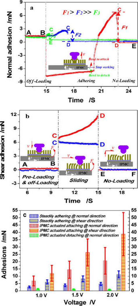
Normal (a) and shear (b) adhesion curves actuated by 1.0 V and results of the normal and shear adhesions at different voltages (c). Red curves illustrate the adhesion when the IPMC was actuated to bend toward the sapphire ball for active attachment. Green curves illustrate the adhesion when the IPMC was actuated to depart from the sapphire ball for active detachment. Blue curves illustrate the constant adhesion when the IPMC stopped working. (a) Changes in force over time are alphabetically labeled A–E. The measurement steps include off-loading (stage A–B), adhering (stages B–C and C–D), and unloading (stage D–E). (b) Similar to (a), there are six changing points labeled A–F and three measurement steps, including preloading and off-loading (stage A–B), sliding (stage C–D), and unloading (stage E–F). (c) Normal and shear adhesions under actuation voltages of 1.0, 1.5, and 2.0 V. Constant adhesion was used as a control. Six measures were taken for each condition and averaged to obtain the mean value.
Shear adhesion, referred to as friction, was generated by dragging the sapphire ball along the PMVS micropillar-patterned IPMC’s surface. Friction forces equaled the difference between points E and F (Figure 9b). The blue curve shows that the detected shear adhesion first decreased and then became stable with a steady shear adhesion of ~6.06 mN because the PMVS micropillars were highly compliant and easily bent toward the sliding direction. The red curve shows that when the IPMC was actuated to bend toward the sapphire ball and the blocking force equaled a positive pressure the detected shear adhesion increased to 12.01 mN, which was approximately two times greater than that without IPMC assistance. This can be further increased by increasing the actuation voltage. The steady shear adhesion was 8.23 and 11.25 mN when preloaded by 1.5 and 2.0 V (Figure 9c). This increased to 26.27 and 38.83 mN when the IPMC was actuated. Therefore, the shear adhesion increased by 0.98-, 2.19-, and 2.45-fold under voltages of 1.0, 1.5, and 2.0 V, respectively. Collectively, increased IPMC actuation significantly improves the shear adhesion between the micropillar-patterned surface and the vertical surface.
Note that the absolute adhesion force is difficult to detect. The adhesion measurement is mainly influenced by two factors: the adhesion force based on van der Waals interactions due to the contact and the elastic force due to elastic recovery of the PDMS elastomer. In the normal direction, the elastic force is opposite, and thus weakens, the normal adhesion. Alternately, in the shear direction, adhesion is strongly coupled with the elastic resistance42–44 and thus is significantly higher than the normal adhesion (Figure 9c).
4. CONCLUSIONS
We report a novel technique to modulate the adhesion and friction of gecko-inspired synthetic adhesives. The IPMC was used as a gecko-inspired artificial muscle to tailor the preload and the normal pressure on the synthetic adhesive. A sticky polymer precursor of PMVS was used to cast the negative Si template obtained by Ar+ plasma etching, yielding PMVS micropillar adhesives with a diameter of 3 µm, a thickness of 10 µm, and a density of 3.8 × 10³ setae/mm2. Graphene oxide carrying Ag nanoparticles was prepared and doped in the Nafion ion-exchange membrane to optimize the carrier transfer, water-saving, and ion-exchange capabilities. After hybridization, the blocking forces of the IPMC increase by 47, 64, and 84% and the stable actuation times increase by 86, 57, and 163% under actuation voltages of 1.0, 1.5, and 2.0 V, respectively. After binding IPMC with PMVS micropillars, the normal adsorption forces were significantly higher than the normal desorption forces; with the assistance of IPMC, the shear adhesion increased by 0.98-, 2.19-, and 2.45-fold, respectively. Collectively, this novel gecko-inspired synthetic adhesive exhibited fascinating reversible adhesion and might be used in unprecedented devices, such as a spiderman-like wall-climbing device.
Supplementary Material
Acknowledgments
This work was supported by National Natural Science Foundation in China (nos. 51275237, 21171150, 21471046, 21441003, and U1304508), Yangtze River Scholar, Innovation Team development plan no. IRT1187, and NHLBI (HL119371 to W.T.).
Footnotes
ASSOCIATED CONTENT
Preparations of PMVS and PMHS precursors, synthesis of GO/Ag NPs and GO/Ag NP-doped Nafion membrane, measurements of ion exchange capability, fabrication and characterizations of the Si negative template, setup for measurements of IPMC electromechanical performance, and adhesion performance measurements. This material is available free of charge via the Internet at http://pubs.acs.org.
The authors declare no competing financial interest.
REFERENCES
- 1.Autumn K, Liang YA, Hsieh TS, Zesch W, Chan WP, Kenny TW, Fearing R, Full RJ. Adhesive Force of a Single Gecko Foot-Hair. Nature. 2000;405:681–685. doi: 10.1038/35015073. [DOI] [PubMed] [Google Scholar]
- 2.Arzt E, Gorb SN, Spolenak R. From Micro to Nano Contacts in Biological Attachment Devices. Proc. Natl. Acad. Sci. U. S. A. 2005;102:10603–10606. doi: 10.1073/pnas.1534701100. [DOI] [PMC free article] [PubMed] [Google Scholar]
- 3.Tian Y, Pesika N, Zeng H, Rosenberg K, Zhao B, McGuiggan P, Autumn K, Israelachvili J. Adhesion and Friction in Gecko Toe Attachment and Detachment. Proc. Natl. Acad. Sci. U.S.A. 2006;103:19320–19325. doi: 10.1073/pnas.0608841103. [DOI] [PMC free article] [PubMed] [Google Scholar]
- 4.Northen MT, Greiner C, Arzt E, Turner KL. A Gecko-Inspired Reversible Adhesive. Adv. Mater. 2008;20:3905–3909. [Google Scholar]
- 5.Zhang H, Long WJ, Guo DJ, Dai ZD. Fabrication and Adhesion of Hierarchical Micro-Seta. Chin. Sci. Bull. 2012;57:1343–1349. [Google Scholar]
- 6.Kim YK, Chung Y, Tsao A, Maboudian R. Tuning Micropillar Tapering for Optimal Friction Performance of Thermoplastic Gecko-Inspired Adhesive. ACS Appl. Mater. Interfaces. 2014;6:6936–6943. doi: 10.1021/am5007518. [DOI] [PubMed] [Google Scholar]
- 7.Hu SH, Xia ZH, Gao XS. Strong Adhesion and Friction Coupling in Hierarchical Carbon Nanotube Arrays for Dry Adhesive Applications. ACS Appl. Mater. Interfaces. 2012;4:1972–1980. doi: 10.1021/am201796k. [DOI] [PubMed] [Google Scholar]
- 8.Murphy MP, Kim S, Sitti M. Enhanced Adhesion by Gecko-Inspired Hierarchical Fibrillar Adhesives. ACS Appl. Mater. Interfaces. 2009;1:849–855. doi: 10.1021/am8002439. [DOI] [PubMed] [Google Scholar]
- 9.Gao HJ, Yao HM. Shape Insensitive Optimal Adhesion of Nanoscale Fibrillar Structures. Proc. Natl. Acad. Sci. U.S.A. 2004;101:7851–7856. doi: 10.1073/pnas.0400757101. [DOI] [PMC free article] [PubMed] [Google Scholar]
- 10.Zhang H, Guo DJ, Dai ZD. Progress on Gecko-Inspired Micro/Nano-Adhesion Arrays. Chin. Sci. Bull. 2010;55:1843–1850. [Google Scholar]
- 11.Huber G, Mantz H, Spolenak R, Mecke K, Jacobs K, Gorb SN, Arzt E. Evidence for Capillarity Contributions to Gecko Adhesion from Single Spatula Nanomechanical Measurements. Proc. Natl. Acad. Sci. U.S.A. 2005;102:16293–16296. doi: 10.1073/pnas.0506328102. [DOI] [PMC free article] [PubMed] [Google Scholar]
- 12.Boesel LF, Greiner C, Arzt E, del Campo A. Gecko-Inspired Surface: A Path to Strong and Reversible Dry Adhesives. Adv. Mater. 2010;22:2125–2137. doi: 10.1002/adma.200903200. [DOI] [PubMed] [Google Scholar]
- 13.del Campo A, Arzt E. Fabrication Approaches for Generating Complex Micro- and Nanopatterns on Polymeric Surfaces. Chem. Rev. 2008;108:911–945. doi: 10.1021/cr050018y. [DOI] [PubMed] [Google Scholar]
- 14.Liu MJ, Jiang L. Switchable Adhesion on Liquid/Solid Interfaces. Adv. Funct. Mater. 2010;20:3753–3764. [Google Scholar]
- 15.Qu LT, Dai LM, Stone M, Xia ZH, Wang ZL. Carbon Nanotube Arrays with Strong Shear Binding-On and Easy Normal Lifting-Off. Science. 2008;322:238–242. doi: 10.1126/science.1159503. [DOI] [PubMed] [Google Scholar]
- 16.King DR, Bartlett MD, Gilman CA, Irschick DJ, Crosby AJ. Creating Gecko-Like Adhesives for “Real World” Surfaces. Adv. Mater. 2014;26:4345–4351. doi: 10.1002/adma.201306259. [DOI] [PubMed] [Google Scholar]
- 17.Gillies AG, Puthoff J, Cohen MJ, Autumn K, Fearing RS. Dry Self-Cleaning Properties of Hard and Soft Fibrillar Structures. ACS Appl. Mater. Interfaces. 2013;5:6081–6088. doi: 10.1021/am400839n. [DOI] [PubMed] [Google Scholar]
- 18.Lee JH, Fearing RS. Contact Self-Cleaning of Synthetic Gecko Adhesive from Polymer Microfibers. Langmuir. 2008;24:10587–10591. doi: 10.1021/la8021485. [DOI] [PubMed] [Google Scholar]
- 19.Guo C, Sun JR, Ge YB, Wang WB, Wang DP, Dai ZD. Biomechanism of Adhesion in Gecko Setae. Sci. China, Ser. C: Life Sci. 2012;55:181–187. doi: 10.1007/s11427-012-4286-y. [DOI] [PubMed] [Google Scholar]
- 20.Murphy MP, Aksak B, Sitti M. Gecko Inspired Directional and Controllable Adhesion. Small. 2009;5:170–175. doi: 10.1002/smll.200801161. [DOI] [PubMed] [Google Scholar]
- 21.Mengüç Y, Röhrig M, Abusomwan U, Hölscher H, Sitti M. Staying Sticky: Contact Self-Cleaning of Gecko-Inspired Adhesives. J. R. Soc., Interface. 2014;11:20131205. doi: 10.1098/rsif.2013.1205. [DOI] [PMC free article] [PubMed] [Google Scholar]
- 22.Reddy S, del Campo A, Arzt E. Bioinspired Surfaces with Switchable Adhesion. Adv. Mater. 2007;19:3833–3837. [Google Scholar]
- 23.Northen MT, Greiner C, Arzt E, Turner KL. A Gecko-Inspired Reversible Adhesive. Adv. Mater. 2008;20:3905–3909. [Google Scholar]
- 24.Drotlef DM, Blümler P, del Campo A. Magnetically Actuated Patterns for Bioinspired Reversible Adhesion (Dry and Wet) Adv. Mater. 2014;26:775–779. doi: 10.1002/adma.201303087. [DOI] [PubMed] [Google Scholar]
- 25.Cui J, Drotlef DM, Larraza I, Fernández-Blázquez JP, Boesel LF, Ohm C, Mezger M, Zentel R, del Campo A. Bioinspired Actuated Adhesive Patterns of Liquid Crystalline Elastomers. Adv. Mater. 2012;24:4601–4604. doi: 10.1002/adma.201200895. [DOI] [PubMed] [Google Scholar]
- 26.Shahinpoor M, Kim KJ. Ionic Polymer–Metal Composites: IV. Industrial and Medical Applications. Smart Mater. Struct. 2005;14:197–214. [Google Scholar]
- 27.Liu S, Liu Y, Cebeci H, de Villoria RG, Lin JH, Wardle BL, Zhang QM. High Electromechanical Response of Ionic Polymer Actuators with Controlled-Morphology Aligned Carbon Nanotube/Nafion Nanocomposite Electrodes. Adv. Funct. Mater. 2010;20:3266–3271. doi: 10.1002/adfm.201000570. [DOI] [PMC free article] [PubMed] [Google Scholar]
- 28.Guo DJ, Fu SJ, Tan W, Dai ZD. A Highly Porous Nafion Membrane Templated from Supramolecule Composite for IPMC Actuator. J. Mater. Chem. 2010;20:10159–10168. [Google Scholar]
- 29.Lee JW, Yoo YT, Lee JY. Ionic Polymer–Metal Composite Actuators Based on Triple-Layered Polyelectrolytes Composed of Individually Functionalized Layers. ACS Appl. Mater. Interfaces. 2014;6:1266–1271. doi: 10.1021/am405090d. [DOI] [PubMed] [Google Scholar]
- 30.Park JH, Han MJ, Song DS, Jho JY. Ionic Polymer–Metal Composite Actuators Obtained from Radiation-Grafted Cation- and Anion-Exchange Membranes. ACS Appl. Mater. Interfaces. 2014;6:22847–22854. doi: 10.1021/am507092p. [DOI] [PubMed] [Google Scholar]
- 31.Lu LH, Liu JH, Hu Y, Zhang YW, Chen W. Graphene-Stabilized Silver Nanoparticle Electrochemical Electrode for Actuator Design. Adv. Mater. 2013;25:1270–1274. doi: 10.1002/adma.201203655. [DOI] [PubMed] [Google Scholar]
- 32.Chandra D, Yang S. Stability of High-AR Micropillar Arrays against Adhesive and Capillary Forces. Acc. Chem. Res. 2010;43:1080–1091. doi: 10.1021/ar100001a. [DOI] [PubMed] [Google Scholar]
- 33.Guo DJ, Zhang H, Fang SM, Tan W, Dai ZD. Fabrication and Adhesion of Bio-inspired Seta: Capillarity-Induced Casting of Porous Silicon. J. Mater. Chem. B. 2013;1:379–386. doi: 10.1039/C2TB00097K. [DOI] [PMC free article] [PubMed] [Google Scholar]
- 34.Gillies AG, Fearing RS. Shear Adhesion Strength of Thermoplastic Gecko-Inspired Synthetic Adhesive Exceeds Material Limits. Langmuir. 2011;27:11278–11281. doi: 10.1021/la202085j. [DOI] [PubMed] [Google Scholar]
- 35.Greiner C, del Campo A, Arzt E. Adhesion of Bioinspired Micropatterned Surfaces: Effects of Pillar Radius, AR, and Preload. Langmuir. 2007;23:3495–3502. doi: 10.1021/la0633987. [DOI] [PubMed] [Google Scholar]
- 36.Hummers WS, Jr, Offeman RE. Preparation of Graphitic Oxide. J. Am. Chem. Soc. 1958;80:1339–1339. [Google Scholar]
- 37.Li D, Mueller MB, Gilje S, Kaner RB, Wallace GG. Processable Aqueous Dispersions of Graphene Nanosheet. Nat. Nanotechnol. 2008;3:101–105. doi: 10.1038/nnano.2007.451. [DOI] [PubMed] [Google Scholar]
- 38.Xie XJ, Qu LT, Zhou C, Li Y, Zhu J, Bai H, Shi GQ, Dai LM. An Asymmetrically Surface-Modified Graphene Film Electrochemical Actuator. ACS Nano. 2010;4:6050–6054. doi: 10.1021/nn101563x. [DOI] [PubMed] [Google Scholar]
- 39.Shahinpoor M, Kim KJ. Ionic Polymer–Metal Composites: I. Fundamentals. Smart Mater. Struct. 2001;10:819–833. [Google Scholar]
- 40.Guo DJ, Ding HT, Wei HJ, He QS, Yu M, Dai ZD. Hybrids Perfluorosulfonic Acid Ionomer and Silicon Oxide Membrane for Application in IPMC Actuators. Sci. China Ser. E. 2009;52:3061–3070. [Google Scholar]
- 41.Guo DJ, Xiao SJ, Liu HB, Xia B, Chao J, Pan Y, You XZ. Diffusion of Hydrosilanes from the Control Layer to the Vinylsilane-Rich Flow Membrane during the Fabrication of Microfluidic Chips. Langmuir. 2005;21:10487–10491. doi: 10.1021/la0514866. [DOI] [PubMed] [Google Scholar]
- 42.Sitti M, Fearing RS. Synthetic Gecko Foot-Hair Micro/Nano-Structures as Dry Adhesives. J. Adhes. Sci. Technol. 2003;18:1055–1074. [Google Scholar]
- 43.Aksak B, Murphy MP, Sitti M. Adhesion of Biological Inspired Vertical and Angled Polymer Microfiber Arrays. Langmuir. 2007;23:3322–3332. doi: 10.1021/la062697t. [DOI] [PubMed] [Google Scholar]
- 44.Ge LH, Ci LJ, Goyal A, Shi R, Mahadevan L, Ajayan PM, Ali Dhinojwala A. Cooperative Adhesion and Friction of Compliant Nanohairs. Nano Lett. 2010;10:4509–4513. doi: 10.1021/nl102398w. [DOI] [PubMed] [Google Scholar]
Associated Data
This section collects any data citations, data availability statements, or supplementary materials included in this article.


