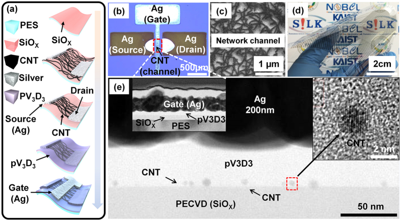
Figure 1. Device schematic and various device images of the printed top-gate CNT-TFTs using 99.9% semiconducting nanotubes.
(a) Schematic diagram showing the printing process scheme. (b) Representative optical image of a CNT network deposited on a substrate. (c) SEM image of the PES surface after CNT deposition. (d) Photograph of the final 44 × 40 device array on a PES substrate. (e) Cross-sectional TEM image of the printed top-gate CNT-TFTs.

