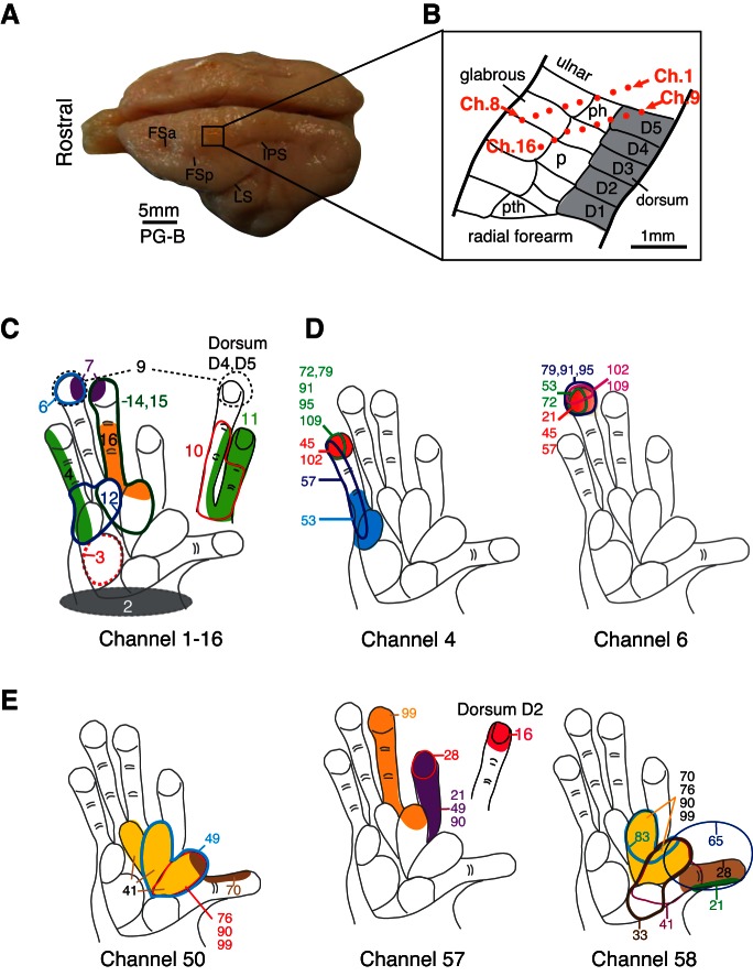
Fig. 1.
Example of the location of a multi-electrode array and neuronal receptive fields (RFs) in galago PG-B indicates that RFs can match the expected cortical somatotopy and may change across different recording sessions from the same chronic implant. A: photograph of the brain for PG-B shows the location of a multi-electrode array in the left hemisphere of somatosensory cortex. Frontal sulcus anterior (FSa), frontal sulcus posterior (FSp), intraparietal sulcus (IPS), and the lateral sulcus (LS) are indicated as landmarks on the photograph. B: schematic drawing shows the approximate microelectrode locations in area 3b of galago PG-B, indicated by orange dots placed on a template based on Wu and Kaas (2003). Positions of the microelectrodes were estimated from tissue reconstructions and from the somatotopy of a hand representation obtained through the array recordings. Ch., channel; D, digit; ph, hypothenar palm pad; P, palm; pth, thenar palm pad. C: neuronal RFs from each electrode channel (numbered from 1 to 16) obtained 60 days after array implantation are shown as examples. Note that their locations and sizes, shown in colored shadings and contours, correspond well to the estimated position of the array in cortex. D: repeated mapping of RFs (colored shadings and contours) for neurons recorded from channels 4 and 6 show examples of RF changes or stability over time. Numbers indicate days since array implantation when the RFs were mapped. Note that RFs obtained from channel 6 were relatively stable over a period of >3 mo, but RFs obtained from channel 4 shifted during the same period. E: examples from area 3a (galago PG-A) of repeated mapping of RFs (colored shadings and contours) for activity recorded from channels 50, 57, and 58 show RF changes over time.

