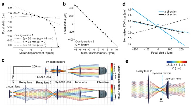
Fig. 2.
Focal shift, back aperture filling and beam path. (a) Focal shift d as a function of mirror displacement D for configuration 1 (single lens). Dots show experimental measurements, lines show theoretical predictions (Eqs. (1), (2)). Black: z-scan lens with fz = 30 mm; gray: z-scan lens with fz = 75 mm. In both cases, xZSU = 75 mm. xz = xZSU – fz gives the deviation from the telecentric arrangement. The dashed gray line shows theoretical prediction for fz = 30 mm and xz = 0, which was not realized experimentally. (b) Configuration 2 (telescope) with fz = 30 mm (xz = 0). The slope of the linear relationship d(D) is 56 μm/mm. (c) Schematic beam paths for single-lens (top) and telescope configuration (bottom). The diameter of the back aperture of the objective is approximately 18 mm. Rays indicate the outer shape of the beam; colors encode the z-scanning position. The focal length/free apertures of the xy-scan lens and the tube lens are 50 mm/30 mm and 200 mm/35 mm, respectively. The relay lenses have focal lengths/free apertures of 150 mm/50.8 mm and 75 mm/50.8 mm for the telescope configuration. Note that filling of the back focal aperture of the objective changes substantially during scanning in configuration 1 (single lens) but not in configuration 2 (telescope). (d) Modulation of FOV size in x and y direction as a function of focal shift d for configuration 2. Dots indicate measurements; solid lines show fits of Eq. (6) with Δw = 7 mm. Dashed lines indicate the theoretical FOV changes for Δw = 7 mm when the x- and y-scan mirrors are equidistant from the focal points of L’2 and L2. (e) Illustration of the separation of x- and y-scan mirrors by Δw = 7 mm in the beam path. All theoretical calculations for beam propagation were implemented in Mathematica, as we show in Code 1 (Ref [21]).

