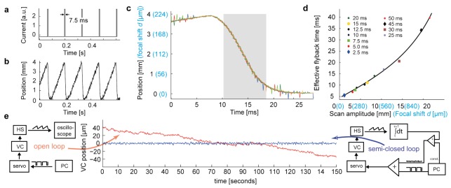
Fig. 3.
Dynamics of the voice coil scanning system. (a) Step current pulses for sawtooth scanning. (b) Displacement of the voice coil motor measured with the position sensor. Small deflections are measurement noise, not positional noise. (c) Overlay of voice coil trajectories (different colors) during four successive flyback periods. Blue values on the y-axis show the corresponding focal shifts for configuration 2. Grey shading indicates the time when no data are acquired (effective flyback time). Steps in the curves are due to digitization. (d) Effective flyback time as a function of scan amplitude (black) and the corresponding focal shift for configuration 2 (blue). Black line is a spline fit. (e) Stabilization of the voice coil (VC) movement. In open loop the position of the VC is not controlled directly, leading to slow positional drift (red). In the semi-closed loop circuit, the positional signal of the hall sensor (HS) is integrated over one z-scan cycle and compared to the setpoint. An error signal proportional to the difference is added to the z-scanning command signal, preventing positional drift (blue).

