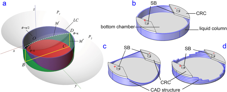
Figure 2. Computer aided design principle.
(a) The cell culture area is shown in red in the bottom chamber; the CAD structure of the top assembly is shown in green, which is formed by intersecting the liquid column (LC, purple) with two paraboloids (P1 and P2, grey). (b) A 3D model of a plain polymeric insert without the 3D CAD structure. The liquid column is shown in blue. Salt bridges are abbreviated as SB. Current rectifying chambers are abbreviated as CRC. (c) A polymer insert model with a smooth 3D CAD structure (blue) to be inserted in a 6-well plate. (d) A 3D model of layered insert (in blue) design to approximate (c).

