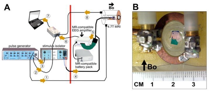
Fig. 4.
(A) MRI-LFP recording apparatus: The magnetic field of the scanner is active to the right of the thick red line. All non-MR-compatible hardware is placed to the left of the red line. The cerebellum is placed in the cradle/tray and is positioned at the scanner isocenter. A surface coil is placed on top of the chamber. The chamber tray has a faceplate that is bolted to the scanner bore using nylon screws. This keeps the chamber level and parallel to the floor. The numbered arrows show the signal flow in this setup: 1 = SYNC pulse, 2 = stimulus timing marker, 3 = trigger pulse to isolator, 4 = current stimulus (delivered to the stimulating electrodes in Cb), 5 = analog LFP signals (from recording electrodes in tissue to amplifier), 6 = digitized LFP signals (fiberoptic cable from amplifier to usb/laptop), 7 = usb input to laptop, 8 = “per-scan” MRI trigger markers. (B) Closeup of tissue submerged in aCSF placed in the chamber. Surface coil is placed on top of the chamber.

