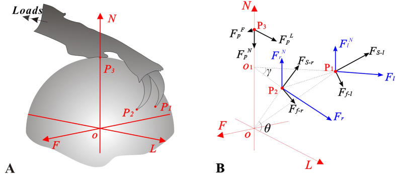
Figure 5.
(A) 3D contact model. (B) The sketch of 3D reaction forces of the biomimetic tarsus devices, where ,
,  and
and  are contact points;
  and
and  are the maximum external lateral and normal forces;
  and
and  are the local support forces and friction forces at the claw tips. Subscripts l and r mean left and right, respectively. θ and γ are the friction angle and the projected angle between the lines running through the claw tips to the sphere centre, respectively.

