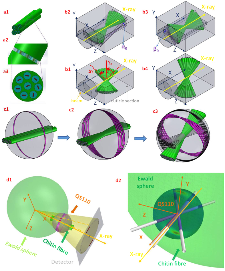
Figure 2. Relation between chitin fibre arrays, fibre symmetry and the diffraction condition.
(a) The randomly oriented reciprocal 110 vectors from each single fibre around the mineralized chitin fibre axis result in smearing of reflections into reflection rings in the sphere described by rotating the reciprocal (110) over all possible 3D directions (hereafter described as QS110 with QS shorthand for q-vector sphere) of the fibre (a1–a3), i.e. a fibre symmetry condition (c1). (b) Schematics illustrating the fibre orientation distribution parameters (γ0, Δγ0) within a single lamella plane parallel to the beam (b1). The variation of fibre orientations will generate multiple intersected rings on QS110, and the rings from continuously distributed fibre plane then smear into a reflection band on the sphere (c2). The yellow arrow in b1 denotes the direction of the incident beam. The fibre planes may tilt in 3D (α, b2), (β, b3) or a combination of both angles (b4) which results in the tilting of the reflection band (c3) on QS110. d1): Sketch of the fibre diffraction geometry, with the Ewald’s sphere shown on left and QS110 on right. The intensity on the intersection ring of the Ewald’s sphere and QS110 will contribute to the diffraction signal. (d2): The intersection of the Ewald’s sphere and QS110 plotted for a specific 3D fibre orientation (the fibre orientation is schematically shown as three white fibres plotted along the main fibre direction and at ± the half width at half maximum away from the main fibre direction). The incident beam directions are indicated in both (d1) and (d2) using yellow arrows. Here, the regions of high scattered intensity appear as distinct red streaks toward the upper and lower parts of QS110.

