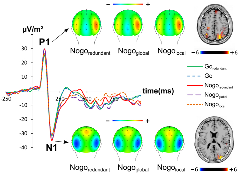
Figure 1. P1 and N1 amplitudes averaged across electrodes P7 and P8.
The y-axis denotes μV/m2 and the x-axis denotes the time in ms. Time point zero denotes the time point of stimulus presentation. The different lines show Goredundant (green), Go (blue), Nogoredundant (red), Nogoglobal (purple) and Nogolocal (orange). The CSD scalp topography plots show the distribution of the scalp electrical potential for the P1 (upper row) and N1 (lower row) on NoGo trials. Warm colors indicate positive and cold colors negative deflections. The corresponding P1 and N1 sLORETA plots are shown besides the respective topography plots and denote the activation differences between the Nogoredundant and Nogolocal condition. The color scale denotes the critical t-values.

