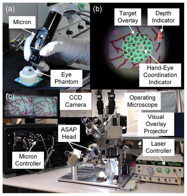
Fig. 1.
Automated intraocular laser surgery system. (a) Handheld instrument (Micron) and eye phantom. (b) Graphical overlays shown through the right eyepiece of the operating microscope. The green circles indicate the targets. The red bar at the upper right corner is the depth indicator representing the height of the laser probe from the retinal surface. The red circle on a target is the guidance cue to maintain the hand–eye coordination. The location and size of the circle represent the lateral and vertical positions of the laser probe, respectively. (c) Overall system setup, including the Micron controller, the operating microscope, the graphical overlay system, and the laser controller.

