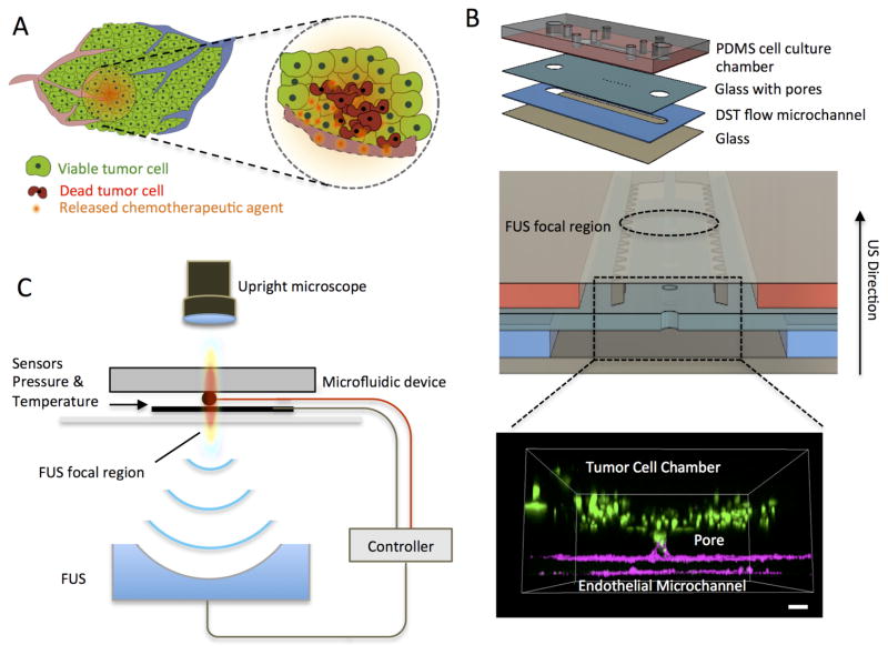
Figure 1.
Schematic of the closed-loop acoustofluidic (FUS-microfluidic integrated) device. (A) Schematic showing localized, drug release in a tumor. The area targeted for drug release by FUS is highlighted with the dashed circle. (B) Top: Assembly of the multilayer microfluidic device. Middle: Cross-section of the microfluidic device showing the cell chamber, DST flow microchannel where the drugs are loaded and the FUS focal region. Bottom: 3D confocal rendering of GFP tumor cells (green) in the cell chamber and interfaced through the glass pore with the DST flow microchannel where an endothelial monolayer is formed (magenta) (C) Diagram of experimental system, highlighting the optically transparent microfluidic device, the pressure/temperature sensors feeding into the controller and the FUS transducer (located 30mm away from the device).

