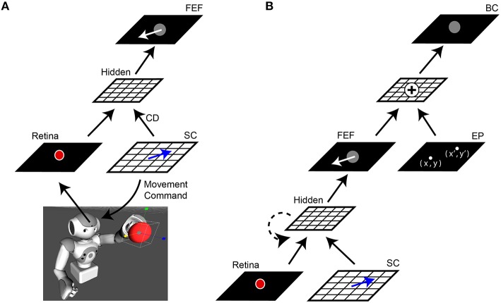
Figure 1.
Network architecture. (A) Central elements of the neural network “core model” that guided the robot. The camera within the robot's head fed visual information, specifically the image of a red ball, to the Retina layer. Movement commands, generated on the SC layer (blue arrows), controlled rotation of the “eye” (i.e., camera fixed in robot's head). A copy of the SC motor command, the corollary discharge (CD) signal, was combined with visual information in a Hidden layer, the output of which reached the FEF layer. The eye movement displaces (in the opposite direction) the projected location of the red ball on the retina and therefore, after an afferent lag, also on the FEF sheet (white arrow). (B) Complete model. The central network in (A) was expanded upon by adding a representation of eye position (EP layer) relative to body. The output of the FEF layer was combined with EP signals to yield a Body-centered spatial representation of the object (BC layer). The output of BC guided the robot's arm to the ball. In some experiments, a recurrent connection was added to the lower hidden layer (dashed line). In all experiments, the training was guided only by the final “behavioral” error in pointing to the ball, with all internal sheets changing to optimize performance of the system as a whole.

