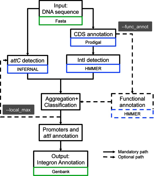
Figure 3.
Diagram describing the different steps used by IntegronFinder to identify and annotate integrons. Solid lines represent the default mode, dotted lines optional modes. Blue boxes indicate the main dependency used for a given step. Green boxes indicate the format of the file needed for a given step.

