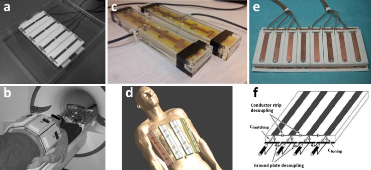
Fig. 15.
Different array coils and setups for renal 7 T imaging: a dorsal array of 8-channel array with microstrip meander elements used by Umutlu et al. (reprinted with permission from [36]). These elements consist of a central conductor over a ground plane, which are connected to each other by capacitors at both ends of the element while the element is fed in the centre. At each end of the element, extra inductance is added by a meander in the central conductor that effectively lowers SAR and reduces inter-element coupling; b setup of a; c two coil elements and d setup used by Hoogduin et al. [53]. The array consists of eight ‘fractionated dipole antennas’. Here, the legs of each dipole are divided into segments and the segments are interconnected by meanders (inductors). This element structure also reduces SAR levels and coupling in comparison to plain dipoles; e anterior array of 16-channel microstrip array used by Metzger et al. [47] (reprinted with permission from [55]). Here, a conductor is placed over a ground plate with capacitors connecting the two at both ends of the element (f). Capacitive coupling is used between the conductors and ground planes of adjacent elements to permit closer element spacing and higher element density. This element is driven from one side, over one of the connecting capacitors

