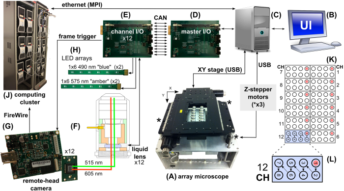
Figure 1. AHTM System Diagram.
(A) The main body of the AHTM showing the 2 × 6 array of 40× objectives and signal paths between components. A user interface (UI) for the system (B) is typically coupled to the master computer (C) which controls XY and Z stage motion and queues instructions to the master I/O board (D). The master I/O board schedules and delivers each instruction to the appropriate channel I/O board (E) using the CAN bus, which in turn, sets focus (F), opens the remote-head camera’s electronic shutter (G), powers the LEDs (H), closes the shutter, and delivers the resulting image to the computing cluster (J), all with less than 1 ms of latency. Experiments require that the user assemble specimens dosed with beads into a conventional 96-well multiwell plate (K). The AHTM visits the entire plate in 7 steps (L). Graphics for (B) and (C) were obtained from openclipart (http://openclipart.org).

