
Figure 2.
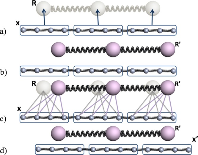
Flowchart of CG-guided hybrid neMD-MC for a 12 particle model system. Big (small) spheres represent the particles in the CG (FG) system. Springs represent bonds. Configuration of the CG (FG) system is represented using R (x). Groups of particles are circled using a blue box. The solid lines between the FG and CG system represent the center-of-mass constraints applied on the FG system using the position of the CG particles. The arrows between the FG and CG system represent the mapping function M. (a) From the initial FG structure x, the CG structure R is built. (b) Dynamical propagation is performed on the CG model, generating a new configuration R′. (c) Dynamical propagation is performed on the FG model, generating a new configuration x′. During this propagation, the position of the CG model is used to constrain the center-of-mass for the FG system. The time-dependent constraints vary linearly in accord with eq 11.